Because of the holidays, TI E2E™ design support forum responses will be delayed from Dec. 25 through Jan. 2. Thank you for your patience.

This thread has been locked.

If you have a related question, please click the "Ask a related question" button in the top right corner. The newly created question will be automatically linked to this question.

SN65HVD233: CANL and CANH waveform

Part Number: SN65HVD233

Hi

Our customer tests this device on their board.

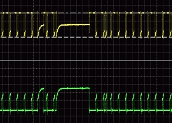
They found the slow rising waveform.  (upper: CANH, lower:CANL)

I understand that there are CAN bus termination between CANL and CANH. 

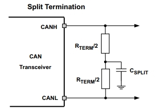
So that , the slow rising may be caused by the termination. (The following termination circuit is connected between CANL and CANH on their board.)

Do you think this waveform is normal?

The differential voltage (CANH-CANL) is normal (no communication error). However I think the rising edge is slower than expected. 

Regards,

Koji Hamamoto

  • Hi Koji,

    Slow rising edges on the CAN bus can be caused by a number of things like the termination circuit, number of nodes on the bus, and the media of the bus itself. Can you please tell me what the split termination cap value is, how many nodes are on the bus, what other transceivers are on the bus, and how long the bus is? Also, could you please provide a better version of the scope capture from above? It is to small for me to read the time scale and really see the waveform good.

    When implementing split termination the most common values we see are 2x60.4ohm between CANH and CANL and a 4.7nF cap to ground.

  • Hi Micheal,

    Thank  you for your reply.

    I will check about your question and get back to you.

    On the other hand, the capacitor of termination is 150pF.  Is that appropriate value?


    Regards,

    Koji Hamamoto

  • Additional information.

    The termination resistor is 56ohm.
    And I will be able to send you the scope capture if you can provide your email address.
    Because those information is confidential.
  • Hi Koji,

    Using a cap value of 150pF will be OK but the cut frequency of the filter will be~17.7MHz. By increasing this cap value to 4.7nF, which is typical, the cut off frequency of the filter becomes 564kHz. This lines up with a CAN data rate of 500kbps. What is your customers data rate? If their data rate is 500kbps then I recommend using the 4.7nF cap value because it will filter more noise that could be harmful to your communication. Here is a short wiki page on CAN termination techniques:

    My email address is mpeffersattidotcom. Please send me the scope captures.