


Part Number: DS90UB964-Q1
Hello,
I'm using the below patgen script with the 964.
According to the datasheets, the default colors for the 8-bar script should be:
['AA' '33' 'F0' '7F' '55' 'CC' '0F' '80']
However, the stream that I’m getting in is:
['AA2A' 'CC0C' '3F3C' 'DD1F' '5515' '3333' 'C003' '2220']
Reordering it as little-endian, followed by the nVidia bitmasking the first/last 2 bits, and bitshift >> 2:
['AAA' '333' 'F0F' '7F7' '555' 'CCC' 'F0' '808']
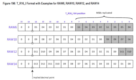
As you can see, it appears that one of the words appear to repeat for each pixel.
- FO --> FOF
- 0F --> 0F0
Is this expected of 8-bit registers filling a RAW12 frame, or am I facing an upstream error?
Resolution, filesizes otherwise look ok to me.
Thanks,
M
################################################################################
# 1920*1080 @ 30 fps
# 4 x lane 800Mbps/lane
# Data Type: RAW12
# Data
#
# Hactive:1920 pixles
# Vactive:1080 lines
# Vtotal:1125 lines
# Vfront:10 lines
# Vback:33 lines
# Pixel size: 12 bits (Mipi CSI-2, Table 25 )
# Block size: 3 bytes (Mipi CSI-2, Table 25 )
# Frame rate: 30 fps
# Number of bars: 8
#
# Reset
board.WriteReg(0x01, 0x01)
# Set CSI_TX_SPEED to select 800Mbps
board.WriteReg(0x1F, 0x02)
#
#
# CSI sel and CSI enable
board.WriteReg(0x32, 0x01) # CSI0 sel and CSI0 enable
time.sleep(0.5)
board.WriteReg(0x33, 0x03) # CSI_LANE_COUNT: 4, EN Continuous Clock
time.sleep(0.5)
board.WriteReg(0x21, 0x80) # Enable CSI Replicate Mode
# enable pat gen
board.WriteReg(0xB0, 0x00) # Indirect Pattern Gen Registers
board.WriteReg(0xB1, 0x01) # PGEN_CTL
board.WriteReg(0xB2, 0x01)
board.WriteReg(0xB1, 0x02) # PGEN_CFG
board.WriteReg(0xB2, 0x33) # NUM_CBARS, Block_size
board.WriteReg(0xB1, 0x03) # PGEN_CSI_DI
board.WriteReg(0xB2, 0x2C) # RAW12 Data Type
board.WriteReg(0xB1, 0x04) # PGEN_LINE_SIZE1: 1920*12/8=2880
board.WriteReg(0xB2, 0x0B)
board.WriteReg(0xB1, 0x05) # PGEN_LINE_SIZE0: 1920*12/8=2880
board.WriteReg(0xB2, 0x40)
board.WriteReg(0xB1, 0x06) # PGEN_BAR_SIZE1: 1920*12/8/8)=360
board.WriteReg(0xB2, 0x01)
board.WriteReg(0xB1, 0x07) # PGEN_BAR_SIZE0: 1920*12/8/8)=360
board.WriteReg(0xB2, 0x68)
board.WriteReg(0xB1, 0x08) # PGEN_ACT_LPF1: 1080
board.WriteReg(0xB2, 0x04)
board.WriteReg(0xB1, 0x09) # PGEN_ACT_LPF0: 1080
board.WriteReg(0xB2, 0x38)
board.WriteReg(0xB1, 0x0a) # PGEN_TOT_LPF1: 1125
board.WriteReg(0xB2, 0x04)
board.WriteReg(0xB1, 0x0b) # PGEN_TOT_LPF0: 1125
board.WriteReg(0xB2, 0x65)
board.WriteReg(0xB1, 0x0c) # PGEN_LINE_PD1:1/(30*1125*10ns)=2963
board.WriteReg(0xB2, 0x0B)
board.WriteReg(0xB1, 0x0d) # PGEN_LINE_PD0:1/(30*1125*10ns)=2963
board.WriteReg(0xB2, 0x93)
board.WriteReg(0xB1, 0x0E) # PGEN_VBP: 33
board.WriteReg(0xB2, 0x21)
board.WriteReg(0xB1, 0x0F) # PGEN_VFP: 10
board.WriteReg(0xB2, 0x0A)
