This thread has been locked.

If you have a related question, please click the "Ask a related question" button in the top right corner. The newly created question will be automatically linked to this question.

DS92LV0421: Signal distortion on the output

Part Number: DS92LV0421
Other Parts Discussed in Thread: DS92LV0422

Dear Sir/Madam,

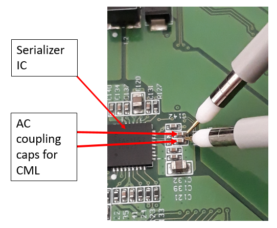
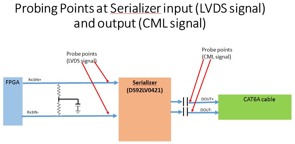
I am using DS92LV0421 as serializer from LVDS input signal to CML output signal. Below is my setup for my measurement:

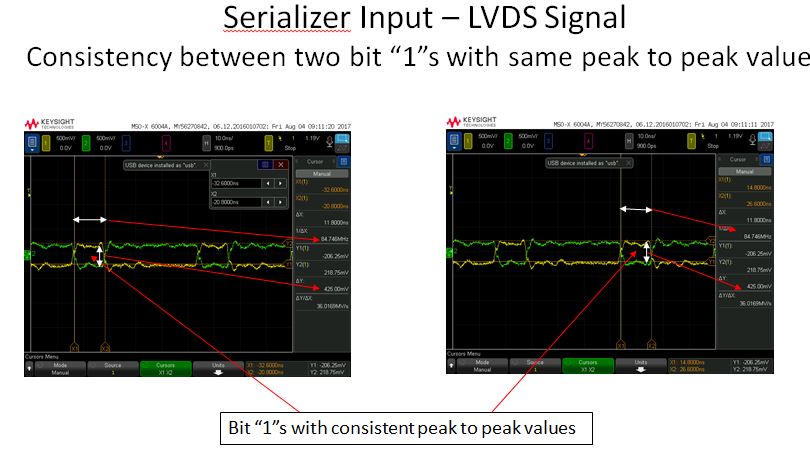
Here is my input waveform, look ok!

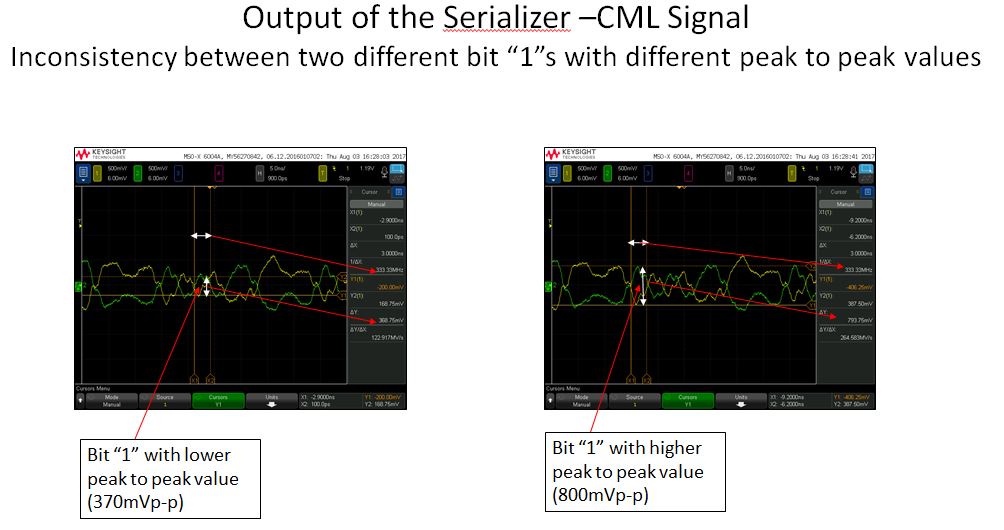
But my output waveform look a bit strange.

With respect to the above mentioned observation we would be grateful if you could help to clarify the below mentioned doubts. 

  1. Is our probing points and methods are correct ?
  2. Why the CML signal at the Serializer output gives different peak to peak values for different bit “1”s ?
  3. If different peak to peak values are acceptable, how to quantify it ?
  4. If different peak to peak values are not acceptable, what is the method to correct it in terms of either hardware or software ?
  5. Do you have any advice how can I improve my CML output?


Just some of the info with respect to our system that could be useful to you.


    • Clock frequency                 =              12 MHz
    • Bit rate per LVDS channel =              12x7       =              84Mbps
    • Bit rate at the CML output  =              12x7x4   =              336Mbps

Best regards,
kpk

  • Hi KPK,

    To assist in the debug of the serializer output, I have a few questions to ask.
    - What is the length of the cable that you are using?
    - What VODSEL setting are you using?
    - Is the receiver at the end of the cable terminated? What is the receiver that you are using?
    - Did you follow the layout guidelines and recommended components as specified in the datasheet?

    Regards,
    Ryan
  • hi Ryan,

    1. Let me show you how I measure the output at the serialiser output. The cable we are using is a VAT6A cable of 43m length. 

    2.  VODSEL pin (pin #20) is connected to 3.3V.

        DE_EMPH pin (pin #19) is connected to the GND through 4.99k resistor

    3. Receiver/de-serializer IC  side is using DS92LV0422, the inputs to the receiver are AC coupled with 100nF capacitors as recommended in the datasheet.

    4. Layout guideline is strictly follow with length matching and components as specified in the datasheet.


    Best Regards,
    kpk