


Part Number: DP83867IR
We are having troubles bringing up our new design with a DP83867IR installed. When linked at 10BaseT the outgoing packet looks nothing likes an Ethernet frame. We can see the TXEN from the RGMII interface go active indicating the MAC has something to transmit but the outgoing MDI transmit doesn't appear to be a valid Ethernet frame. See attached included picture.
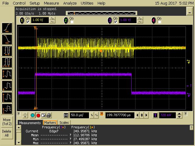
Zoomed into an smaller area shows the following.

Not quite sure how to describe this as seen on the MDI interface but almost looks like a much shortened PREAMBLE with an end of frame indication. As you can see in the previous image there are several with the time that RGMII TXEN is active.
We have verified the RGMII timing is what's expected. Our routes are matched consequently we've strapped the RX and TX RGMII clock to 2.0ns to meet timing. After inspecting the registers the strapping reads correctly.
Below is a received packet on the MDI interface and the corresponding RGMII RXEN as expected.
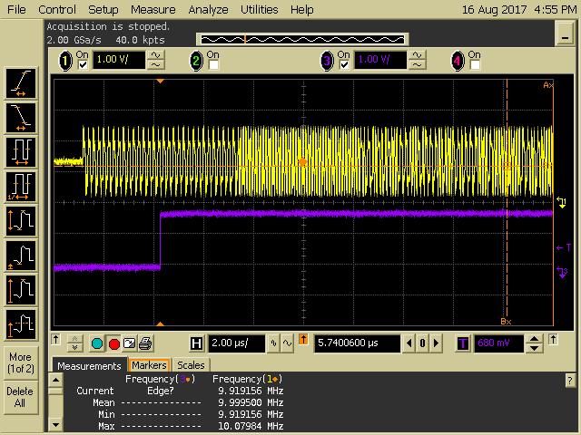
I realize its a little hard to see but there is PREAMBLE, SFD along with packet data.
Here is a register dump with differences shown from reset values to MAC attempting to send a PING.
| Register Name | Address | Value @ Reset | Value Post Ping | ||
| #BMCR | 0x00 | 0x1140 | 0x1140 | ||
| #BMSR | 0x01 | 0x796D | 0x796D | ||
| #PHYIDR1 | 0x02 | 0x2000 | 0x2000 | ||
| #PHYIDR1 | 0x03 | 0xA231 | 0xA231 | ||
| #ANAR | 0x04 | 0x10 | 0x10 | ||
| #ANLPAR | 0x05 | 0x450 | 0x450 | ||
| #ANER | 0x06 | 0x65 | 0x67 | Diff | Link Code Word Has Been Received |
| #ANNPTR | 0x07 | 0x2001 | 0x2001 | ||
| #ANNTRR | 0x08 | 0x0 | 0x0 | ||
| #CFG1 | 0x09 | 0x200 | 0x200 | ||
| #STS1 | 0x0A | 0x0 | 0x0 | ||
| #1KSCR | 0x0F | 0x3000 | 0x3000 | ||
| #PHYCR | 0x10 | 0x4040 | 0x4040 | ||
| #PHYSTS | 0x11 | 0x6C02 | 0x7C02 | Diff | Page Received |
| #MICR | 0x12 | 0x0 | 0x0 | ||
| #ISR | 0x13 | 0x0 | 0x1C44 | Diff | Page Received Int., Auto Negotiation Complete Int., Link Status Change Int., MDI Crossover Change Int., Wake On LAN Int., |
| #CF2 | 0x14 | 0x29C7 | 0x29C7 | ||
| #RECR | 0x15 | 0x0 | 0x0 | ||
| #BISCR | 0x16 | 0x0 | 0x0 | ||
| #STS2 | 0x17 | 0x40 | 0x40 | ||
| #LEDCR1 | 0x18 | 0x6150 | 0x6150 | ||
| #LEDCR2 | 0x19 | 0x4444 | 0x4444 | ||
| #LEDCR3 | 0x1A | 0x2 | 0x2 | ||
| #CF3 | 0x1E | 0x2 | 0x2 | ||
| #CTRL | 0x1F | 0x0 | 0x0 | ||
| #TMCH_CTRL | 0x25 | 0x400 | 0x400 | ||
| #FLD_CFG | 0x2D | 0x0 | 0x0 | ||
| #CFG4 | 0x31 | 0x10B0 | 0x10B0 | ||
| #RGMIICTL | 0x32 | 0x00D3 | 0x40D3 | Diff | Reserved… |
| #RGMIICTL2 | 0x33 | 0x0 | 0x0 | ||
| #100CR | 0x43 | 0x07A0 | 0x07A0 | ||
| #STRAP_STS1 | 0x6E | 0x0 | 0x0 | ||
| #STRAP_STS2 | 0x6F | 0x100 | 0x100 | ||
| #BICSR1 | 0x71 | 0x0 | 0x0 | ||
| #BICSR2 | 0x72 | 0x0 | 0x0 | ||
| #RGMIIDCTL | 0x86 | 0x77 | 0x77 | ||
| #LOOPCR | 0xFE | 0xE721 | 0xE721 | ||
| #RXFCFG | 0x134 | 0x1000 | 0x1000 |
At this point we are at a loss as to what to look at next. Any pointers?
Thanks, Gary
