


Part Number: TLK110
Other Parts Discussed in Thread: TLK105
Hello TI E2E Community!
We encountered several cases of TLK110 component failure (loss of function due to the reasons I'm seeking help to figure out with this post).
Description
Please consider our implementation of one of two identical channels for AFDX (100 Mb/s operation only no auto-negotiation, see ARINC 664):
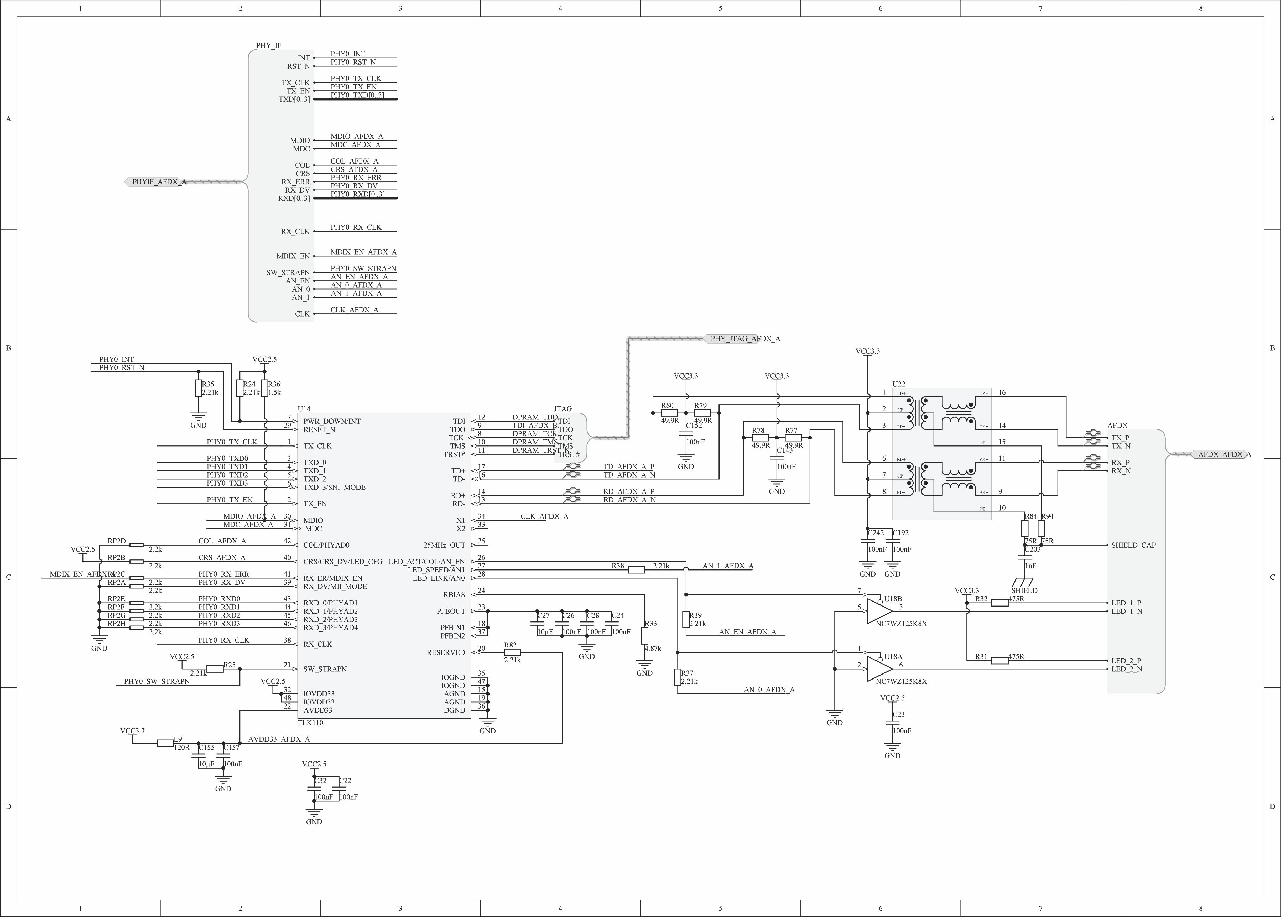
U14 - TI TLK110
U22 - Würth Elektronik 749010012A 1422, Transformer, LAN, 1 Port, 100 Base-T, 1500VAC, 350µH, 1:1 Turn Ratio
U18 - Fairchild Semi NC7WZ125K8X, Buffer/Line Driver 2-CH Non-Inverting 3-ST CMOS 8-Pin US T/R
L9 - ferrite bead 120R, Murata, BLM15AG121SN1D
Differences
Differences from the user manual, Figure 3-1. "Power Connections for Single Supply Operation":
- C242 = 100nF (recommended 1uF)
- In the UM there are x2 C242 and x2 C192
- Pin 22 circuitry: L9 & C155=10uF & C157=100nF
The Problem
The problem is that at the time span of weeks-months at several locations under normal environmental conditions one of the two identical channels of our boards (see picture above) would fail and stop functioning (no link, nothing). Our initial guess was boards mishandling / statics / high AC voltage in transceiver RX/TX lines but having encountered 4 such cases in less that a year and taking into consideration high variance in failure conditions, board handling and usage scenarios (loopback testing - ch.A to ch.B, connection to Cisco switch with no PoE, communication with avionic switch) we started having doubts.
Measurements
Having myself tried measuring some of one of the failed boards components parameters with DMM Fluke 179 (which I know is not the best way) I found the following deviations of the failed channel in comparison to healthy one of the same board and healthy ones of 3 other identical boards:
- Capacitance measured at C28 contacts while still soldered to the board (capacitor very close to Pin 37 PFBIN2): 10.1uF (instead if ~105uF for healthy)
- Resistance measured at C28 contacts while still soldered to the board: growing resistant measurement from ~12kOhm to ~100kOhm (instead of ~12kOhm for healthy), sometimes it can grow up to ~430kOhm
- Resistance measured at R33 contacts while still soldered to the board (resistor very close to Pin 24 RBIAS): 4.87kOhm (instad of 4.49kOhm for healthy)
Hence it looks like the internal voltage regulator (PFBOUT, PFBIN1, PFBIN2) is electrically damaged. We consider this to be secondary problem, a consequence of some other problem.
Question
- Have you gentlemen (and ladies) ever encountered a similar problem / use case?
- Do you think our implementation may contain some flaws which could under some conditions cause such TLK110 PHY failure?
- Do you think I should have executed more measurements in addition to the listed above?
- Most importantly do you maybe have an idea what could have caused such failure?
Very hopeful and with best regards
Alexey
