This thread has been locked.

If you have a related question, please click the "Ask a related question" button in the top right corner. The newly created question will be automatically linked to this question.

PCA9306: Strange behaviour on clock/data lines: glitches and dead line

Part Number: PCA9306

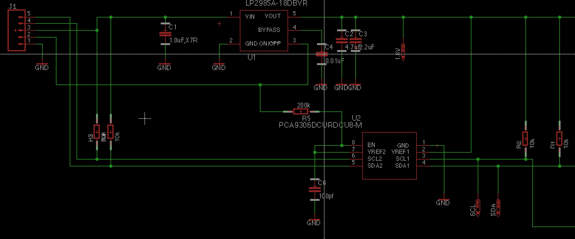
I am trying to use a PCA9306 for I2C level shifting from 3V3 to 1.8V. I can see that the signals are shifted correctly on one channel but not on the other one. The implemented configuration is the one suggested in the datasheet.

Is there any specific reason for this behaviour?

Best regards

  • Hi Marco,

    That's strange - can you tell us any more about the channel that is not showing the correct shifted values? What do you see instead? Is there a signal waveform capture that you could send us to review?

    Also, can you please confirm that you have pull-up resistances used on both sides of the device? If so, what are their resistance values, and to what voltage do they connect?

    Do you have VREF2 and EN tied together and pulled to your 3.3-V supply through a 200-kOhm resistor as shown in Figure 7 of the datasheet?

    Regards,
    Max
  • The following is the schematic implemented in the PCB.

    As you can see there are 10k generic pullups to both sides. and the board behaves fine if the signals are pulled low manually with a switch to ground either from the high side, either to the low side.

    The issues appear when I drive this board with an external microcontroller board. 

    What I see is the working line is very glitchy at the beginning of each front and the second line is pulled constantly low except for some glitches.

    I can provide picture of the schematic and as soon as possible I will provide also waveforms

  • Hello Marco,

    The PCA9306 looks like it is connected to correctly.  One thing I might look at is the ON/nOFF pin of U1.  If there is noise on this then you might be having problems.  You may also want to have a decoupling cap on the EN-VREF2 connection to ground. 

    Lets get waveforms, then we can see what might be going on.

    -Francis Houde

  • Thanks for you support.

    I added mode decoupling on the ON/OFF pin for U1 and on EN/VREF2 (100pF each side) and lowered the PullUps from 10K to 2K2

    This solved all the issues and now the Logic Shifter works perfectly.

    Best regards