This thread has been locked.
If you have a related question, please click the "Ask a related question" button in the top right corner. The newly created question will be automatically linked to this question.
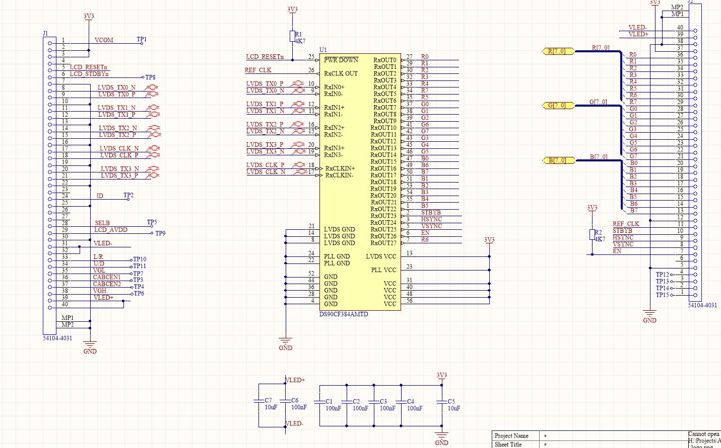
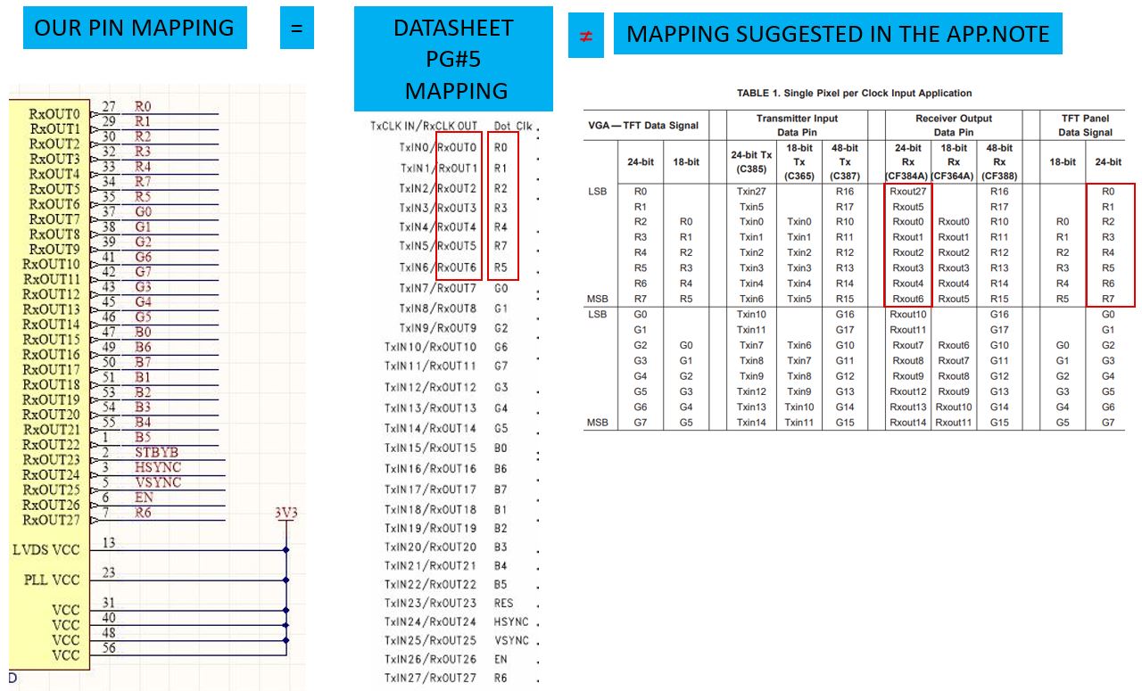
Hello, I am using DS90CF384AMTD to interconnect LVDS from the controller to a RGB LCD. Have used RxOUT0-27 as RGB+Control signals as shown in the pg#5 of the datasheet (Figure 4. “16 Grayscale” Test Pattern (DS90CF384A)). But we don't see any image in the LCD. I measured proper 50MHz clock art RcCLK, but the RES pin is keep on toggling and all the R,G,B signals also look noisy. (*Note*: LCD controller SW is also not complete, It is configured for a LVDS LCD with different resolution, so it can be a SW issue as well). What are the basic checks I can do to ensure that there's no hardware issue. Please find attached my schematics and suggest. Thanks.
Hello Pon,
This sounds like a mapping issue.
You must make sure you are mapping on the inputs serializer is what you want on the output deserializer.
Here is a link to suggested mapping that the industry follows: www.ti.com/.../snla014.pdf
Regards,
Hi Darryl, Thanks for the response. We followed the pin mapping as per the datasheet pg#5 (refer attached snapshot). Which is completely different from the one mentioned in the app.note you shared. Where did we go wrong? Can you please help us to understand better why/what is different in the datasheet map. Will changing the pin map as per the app.note solve the issue? Thanks.