This thread has been locked.

If you have a related question, please click the "Ask a related question" button in the top right corner. The newly created question will be automatically linked to this question.

TPS65981: Configuration tool and HPD issue

Part Number: TPS65981

Hey team,

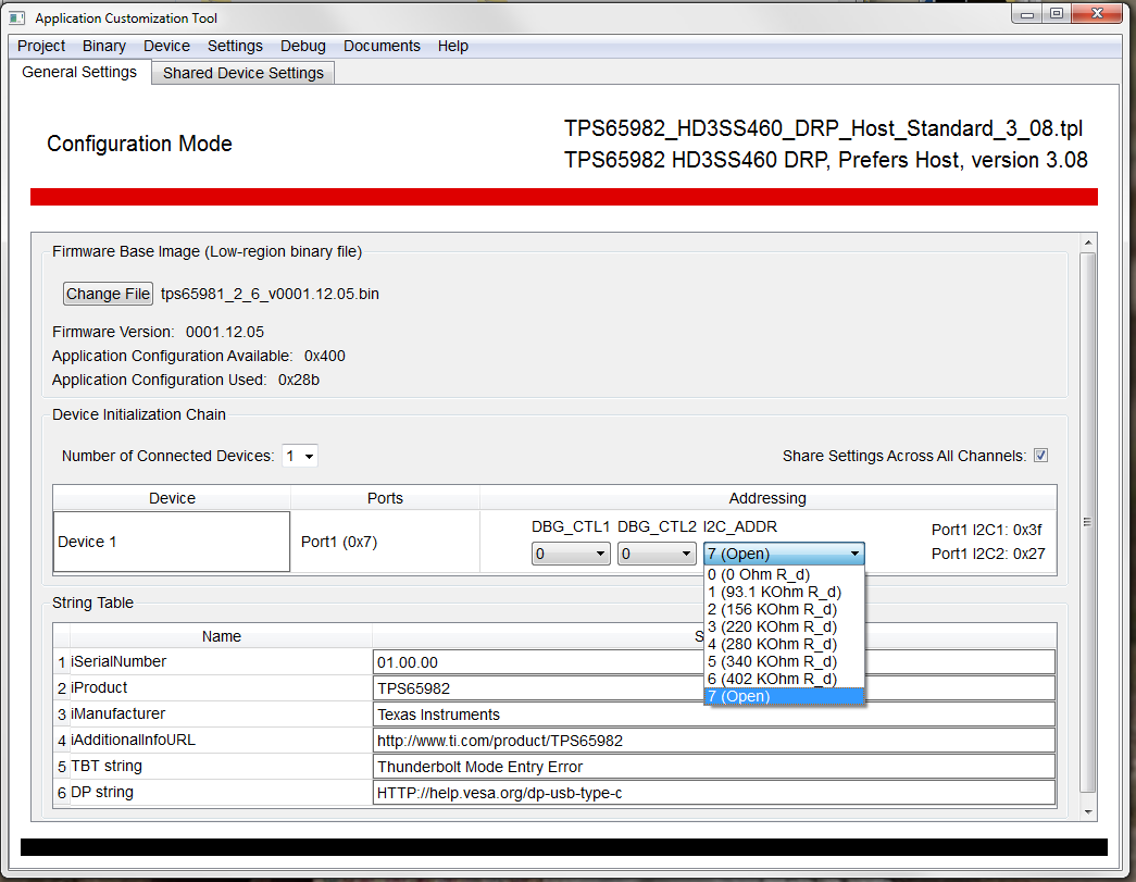
I am running into trouble with the new version of the configuration tool, specifically with the "debug mode" The device is configured and works with the address 0x27 when the Aardvark is used manually and through the utilities GUI, but with the debug mode it seems to be cycling between address 0x20 and 0x38. How can I tell it to use address 0x27? it will not connect otherwise.

The other issue I'm facing is with the HPD line, I have a DFD/Source device which plugs into a Display (UFD/Sink), and they are meant to communicate via DisplayPort. The source is currently configured as "GPIO 4is HPD transmit and receive" however, GPIO 4 always seems to be high whether the Display is plugged in or not, the Display seems to work, but the GPIO always show high. then in the Utlities GUI, the HPD shows up as low for both transmit and receive, so I am getting conflicting information, can someone help explain?

Thank you!

best regards,

Saqib Mohammad

  • Hi Saqib,

    In order to change the I2C address that the debugger will connect on, please change the pin strapping in the "Device Initialization Chain" section on the "General Settings tab" as shown below.  As you change the DBG_CTL1/2 and I2C_ADDR values, you will see the effect on the I2C1 and I2C2 port addresses.  These are pins on the TPS6598x device that can be pulled to 3.3V or Ground (for the DBG_CTL) or strapped with a resistor value (I2C_ADDR).

    If you set I2C_ADDR to "7 (open)" it should give you the address you are looking for. 

    For your second question, let me give you a few high-level pointers, and if you need more detail, please post to a separate thread so that we can close the first issue and keep the second open if necessary.

    Basic Starting Checklist:

    1. Please verify that the DP alternate mode has been entered.  If this mode has not been entered, then the HPD will not be passed over PD.

    2. More detail on how to verify this is in the following app note:  http://www.ti.com/lit/an/slva844a/slva844a.pdf

    3. If you have verified that DP mode is entered, then there is a sequence of three events to verify:

    a.  Firstly, the HPD line leading into the TPS6598x on the DP UFP side must go high

    b.  Then you should see an Attention message (assuming it is a USB UFP) sent from the DP UFP to the DP DFP using a PD analyzer

    c.  Finally, when the DP DFP receives this message it should drive the GPIO4 line high on its side.

    Regards,

    Steve

  • Hey Steve,

    Thank you for your feedback, the first issue has been resolved, thank you!

    The HPD is still uncertain, the customer is seeing odd behavior:

    "

    Measuring the physical signal, it is always high whether I have a display plugged in or not. To add insult to injury, the debug registers for GPIO status and DP status report the opposite – GPIO4 is always low and the HPD state is always low.

    "

    I will email you the project file if you do not mind reviewing it, I do not want to post it here.

    Thank you

    best

    Saqib Mohammad