This thread has been locked.

If you have a related question, please click the "Ask a related question" button in the top right corner. The newly created question will be automatically linked to this question.

SN65HVD1780: Dip in the Rx waveform

Part Number: SN65HVD1780

HI,

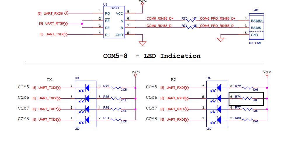
We used SN65HVD1780 as the RS485 line driver in our product .While measuring the R and D wave form we found the below observation.

The R signal which is the receive signal (TTL) is having a dip when the D (transmit) signal is active . The R signal which is usually high when idle will have pulses when it is receiving . 

During the reception the signal is ok and there is no Dip observed in the D line (transmit)

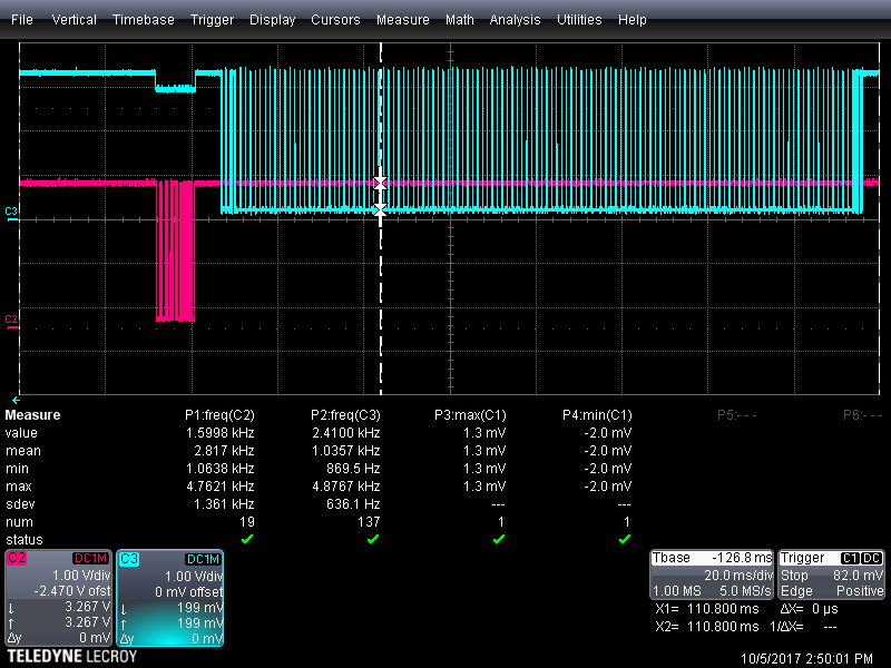
Please see the below graphs

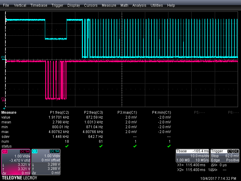
Blue is R and red is D. please clarify why such a dip is observed in the R signal

Regards

Eby

  • Hi Eby,

    I've tried to understand your problem and so far I still need some info from your side. As a matter of fact I would like to know if you are connecting both  DE pin and RE# pin. Could you provide values or measurements of those pins?

    When RE# is logic low the receiver is enabled but in order to send data, DE must be logic high in order to be in driver mode.

    The R pin dipping almost at half dynamic could be caused by different sources driving that node, so as a first suggestion I would try to see if by inserting a pull-up resistor onto the R pin could be helpful. This would keep the R pin high during the receiver disabled phase, as R shows a high impedance at this point.

    Looking forward to your inputs.

    Best regards,

    Adrian

  • HI Adrian,
    Thanks for the reply

    The RE# and DE are having correct logic . Have verified the same .
    We are wondering why this R pin is dipping .

    I have tried with a 10K pull up and observed that there is an improvement and the dip has reduced by about 1V . now the dip is very small.
    As of now we are having only one node
    But i would like to know the reason for the dip .

    And one more thing , i believe the R dips simultaneously when the DE is enabled .


    Regards
    Eby
  • Hi Eby,

    the number of nodes shouldn't influence the dip that you're measuring.

    Have you tried different values of pull-up resistors? By using smaller values the dip should decrease.

    When in driving mode, the R pin in its high impedance status and the receiver output current is max 1 microA, which I guess is not the value that you still see in the dip.

    Another cause could be the load that the R pin has. In this case the MCU could present a resistive path that creates a voltage partition.

    Could you please provide to me measurements of the R pin with different pull up resistors, and also Vcc if it's different than what you expect.

    Please let me know.

    Thank you and best regards,

    Adrian

  • HI Adrian,

    The waveform with 10K pull up on the R line shared below . We have seen the Dip with Different processors interfaced with the same RS485 chip.

  • Hi Eby,

    have you tried different values of pull-up resistors? Even in that case do you still see the same dip?

    In order to understand better the problem I need to know better what is the impedance seen from the R node, I believe something else might be driving that node and influencing the dip.

    Moreover, have you checked the behavior of the power supply? It could be that during the Driving phase, because the driver is requiring a lot of current, the Vcc could drop due to some limitations.

    Please let me know.

    Regards,

    Adrian

  • HI Adrian,

    I have not tried with different pull up . From the above graph i feel like as stronger pull up will have a lesser or no dip

    Regarding the impedance seen from the R node . How can we measure / calculate the same ?

    Our power supply have adequate capacity to drive enough current to the transceiver .

    How much margin should we consider for a single Transceiver ?

    Regards
    Eby
  •  HI

    Please find the graph with 3.3K pull up on R line

  • Hi Eby,

    so with a smaller pull-up resistor you measure a smaller dip.

    To me it seems that something is pulling down that node. Probably some leakage current. Could you tell me if there is anything else on the R pin node? Maybe show part of the schematic that is specifically showing everything connected to that node. Maybe a protection diode leaking current? If that's sensitive for you, we could discuss about this via email.

    Would be helpful to have also a measurement of the bus lines from the receiver. Typically they are called A and B nodes.

    Have you tried testing different boards and/or different devices? This is order to understand where the problems stands. One of the two could have been damaged and the ESD protection could be leaking.

    Now onto your questions:

    - You can measure the impedance at that node by calculating V and I at that node. Simply using a multi meter in series or parallel.

    - Margin on the transceiver, you mean on the bus lines or the output voltage?

    Let me know if you have more info.

    Thank you and best regards,

    Adrian

  • Hi Adrian

    Yes with a stronger pullup the Dip is reducing 

    If something is pulling the R node down during the TX time - Why there is no dip during the Idle state ?

    We are having Three cases

    1. NXP processeor...> PCIE interface --->> PCIE-UART Converter---> RS485 transceiver

    2. NXP processor---->UART----> shared with RS485/RS232 used based on selection in software

    3. Atmel Processor --->UART----->shared with RS485/RS232 used based on selection in software

    In the case where we use the RS485/RS232 , the RS232 transceiver is disabled and shutdown when RS485 is in use .

    When the RS232 is active RS485 is kept in the Idle state .

    In all the above three cases we are seeing the DIP

    The Protection TVS is used in the A-B lines(D+,D-)

  • HI Adrian
    One more doubt
    Will adding a strong pullup on the R node affect the communication .
    Now 3.3K is a Strong Pull up. May be 1K will almost eliminate the Dip in the R node . But will it have an impact on the communication on a later point of time .

    Regards
    Eby
  • Eby,

    what do you mean with Idle state? Because the device enters a low power stand-by mode when both driver and receiver are disabled. In that condition R pin goes high impedance.

    Have you tested different devices or kept using always the same? Could be a problem from our device as much as from the board itself.

    Regards,
    Adrian
  • HI Adrian,

    We have seen the same dip while using MAX3430 from Maxim IC also.

    Observed in different products with different processor/ controller

  • Hi Eby,

    I don't believe that the combination of RS485/RS232 is the problem. As you said, you are facing the same problem also when only using the RS485. Moreover, when not used, the transceiver should be idling at high impedance.

    Regarding the pull up resistor, have you tried with the 1k value? It should not present major problems when in receiver mode and driving the R pin. Do you know if the uC that you're using has already an internal pull up resistor?

    After the testing that you've presented to me, even using to different devices, you still measure the dip; I would think of a leakage created within the testing board.

    Please let me know how these final simulations run.

    Kind regards,

    Adrian

  • HI Adrian,

    Yes , RS232/485 combination is not the issue as we are seeing the issue with RS485 alone

    also one thing  common in all our design is the TVS diodes used. The TVS diodes are connected to the A,B pine (D+ and D-)

    Could this have an impact on this ?

    We are trying to measure the R line with the TVS removed to See if the Dip persists 

    Regards

    Eby

  • HI Adrian,
    I have tried removing the ESD diode in the line but it doesn't have any impact. the dip is still there
  • HI Adrian,
    Yes the RS232/485 combination is not the issue because it is observed with RS485 alone
    The Pull seems to be the solution for this observation but the root cause of the issue is unknown
  • Hi Eby,

    thank you for updating me. Yes I agree, the TVS diodes shouldn't be an issue with the R pin in fact they could affect only the two buses.

    Since you have tried different components and the problem was there, tried different micro controllers and the dip was still there, what I could suggest as a last testing to do, would be to take the device off the board and perform some measurements on that board. Could be that the leakage is coming from the board itself.

    I am glad that you found a solution by using the pull up resistor.

    Let me know if anything else comes up.

    Kind regards,

    Adrian

  • Hi Adrian,

    Yes , the dip is there with a different Micro controller also .

    There is one more observation. There is a an LED indication from this pin, i tried removing the resistor and found that the DIP was even worse. R74 was removed and found that the DIP was even worse 

    Regards

    Eby

  • Hi Eby,

    thank you for sharing this part of the circuitry. Yes, the R74 is working in this case as a pull up resistor for the LED and as a current limiter. When the RXD6 pin goes low, the LED is turned on and vice-versa when RXD6 is high the LED is off. By taking off the R74, you lose the ability to pull up that node towards V3P3. This is manifested in an increased dip at the R pin.

    Have you done any testing on the other resistors too? For my knowledge the same behavior should happen also to RXD5, RXD7, RXD8.
    This is still proving the fact that the R pin (RXD6) shows some leakage.

    Please let me know if you have any other info.
    Regards,
    Adrian
  • Hi Adrian,

    I had tried removing all the resistors and the behavior is the same for RX5-RX8 lines .

    Yes I understand that the Resistor is acting as a pull up .

     So if we didn't had a pull up , it would have been worse i guess.

     One this we noticed is that ,if we don't have the pull up and the LED-Resistor combo , there was unwanted junk characters received at the node even if no source is connected to it .

    Is there anything else that we can check from our side on this circuit .

    Regards

    Eby

  • Hi Eby,

    (Adrian is out of the office this week, so I will try to fill in.)

    I think this portion is well understood, but just to be totally clear - the voltage level on the R output is expected to be different depending on whether the receiver is enabled or not (i.e., whether the /RE pin is high or low). When the receiver is enabled, the output is driven via a low output impedance and will be either close to the VCC supply or close to the transceiver's ground. When the receiver is disabled, the R output is high impedance and thus the voltage will "float." This means that it will not be strongly biased to any particular voltage, and so its value will depend on whether it is pulled high or low externally, what kind of loading is present, etc.

    It looks like in this case using the pull-up resistance is effective in ensuring a high logic level on the R output while the receiver is enabled. If you are concerned about the voltage being lower than you would expect, though, then it would be important to understand what may be sinking leakage current from this voltage node.

    What connects to this node? From this thread it sounds like there are just a few things: the transceiver output, a pull-up resistor, an LED indicator, and a logic input to a microcontroller. Is there anything else? If not, then most likely the leakage currents would come from either the MCU, the transceiver, the PCB, or the oscilloscope probe used in this measurement. (By the way, what is the input impedance of this scope probe?). You could see which component is having the strongest effect by removing them and seeing if the measured voltage increases. For example, if you removed the transceiver and measured the voltage on the "R" line (using the same measurement set-up), I would expect you to measure the same voltage as during these periods when the receiver is disabled (since in that state we expect the receiver output to sink or source less than 1 uA). If you saw a much higher voltage, though, then we would know that the lower voltage is somehow related to the transceiver.

    I hope this makes sense - please let me know what further questions you have.

    Regards,
    Max
  • HI Max

    Thanks for your reply ,

    One thing  is that the Dip in the R is only noticed when then the RS485 chip is transmitting. On other situation like when there is no transmit and receive there is no Dip noticed

    The issue is not observed when the Receiver is enabled . The issue is actually observed when the Driver is enabled .

    The R is dipping when the Driver is enabled and when the receiver is enabled the R signal is OK.

    Yes we want to know the node which is sinking this current .

    This is a basic block level representation of the interface .

    We are measuring the Waveform with the DC-1Mohm mode 

    We will check the signal with the transceiver removed and will update you the status of the same 

    Regards

    Eby

  • HI Max,

    I tried removing the transceiver and measured the waveform.

    Now what I observed is that the R line measures 1.6V continuously which was the amount of DIP we measured with the transceiver.

    So from the test I understand that the issue is not with the transceiver and something is having an impact from the rest of the circuit .

    To confirm that is was not the issue with the DSO I measured it with the Multi-meter

    So the source is from the Board may be the processor Pin might be pulling it down .

    And I guess the Pull up resistor addition on the R value or adding a buffer or something will make a difference .

    Thanks for the support 

    Regards

    Eby 

  • Eby,

    Thanks for following up with this information, and I'm glad you are getting closer to discovering the root cause. It sounds like it's probably worth checking into the input resistance of the processor's input next to see if it might be the source of pull-down current.

    I'm not sure what else we could assist with if the issue is not related to the transceiver device, but please continue to feel free to contact us if you feel there is any help we can provide.

    Best regards,
    Max