This thread has been locked.

If you have a related question, please click the "Ask a related question" button in the top right corner. The newly created question will be automatically linked to this question.

SN65HVS885: Weird input data

Part Number: SN65HVS885

I'm trying to communicate with a raspberry pi 3
input's are driven by 12V and leds are connected to led drives.

The data on SPI connection is weird.
For example if i had 120 as binary on leds i had 126 on spi output.
And if i add 2 126 stays the same.
take away 2 and it rockets down to 80.
I can never predict.
I'm running the SPI on
mode0 (But tried all 4)
8bit datalenght
Pulling the LD input down and up before CE input.
I don't know what i'm doing wrong.

  • Hi Tahir,

    We do not have Raspberry Pi 3 schematic. Is it possible to send us as a reference? Then we can better understand your question regarding SN65HVS885.

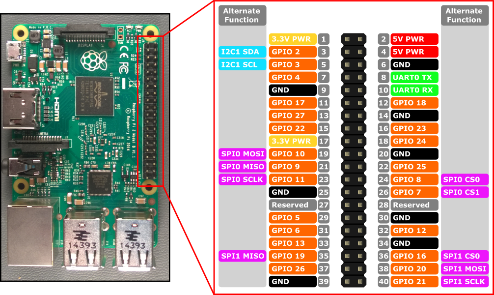
  • SPI0 MISO is connected to pin 23 on SN65HVS885
    SPI0 MOSI is connected to pin 27 
    SPI0 SCLK is connected to pin 25
    SPI0 CS0 is connected to pin 24
    Also pin 29 gpio 5 is connected to pin 26
    I don't really have a schematic but i hope this is enough.

    I need this interface for a encoder reader that i'm building, i need to use spi or i2c for input readings.
    (I know encoder only uses only 2 inputs but i'm also using another chip for high speed reading and it gives 8 bit output)

    From my trials 
    - if i turn 1 of the inputs high the readings are all correct.   press 8th button and 8th bit becomes high and so on.
    - if i press a less significant bit and a higher one together then the higher bit location is correct, but the lesser bit is lit up in a greater bit place.
    For example
    just press 7th button    output is 7th bit
    then press 2nd button together with 7th   and the output is    7th and 3rd bit.

    Also if i press first 4 buttons together   first 4 bit goes high
    But if i depress only 3rd button the output of only 1st bit goes low. 2 3 4 is still high.
    All the while the led drives are correct the output i read from spi is wrong.

    I've tried this in all 4 spi modes.
    Also tried taking Spi data input on sn65hvs885 to high as said in datasheet but the data i get then is much more hectic.

    Also, sorry i didn't understand completely what did you mean by schematic i hope this is alright.
    On another note I am not particularly inseparable with this chip so if anyone knows another that i can use in this way that'd be great.

    Also thanks for the answering. Expected someone to just say hey you posted it in the wrong place or something :)

    Edit: i've noticed that it's a bit hard to imagine what's going on with problem so i made a small video of it and posted in youtube,
    https://www.youtube.com/watch?v=NHKmhMxjYCo

  • Hi Tahir,

    Thanks for taking the video for me to quickly catch what you need. Besides, your system level block diagram is enough. I requested schematic because I assume you have schematic instead of system level block diagram.

    I suspect most likely it is the debounce issue when you press the switch. Below is any voltage waveform example that from logic low to logic high. You can see the transition window. 

    If the DB0 and DB1 are grounded for now, please float both. DB0 and DB1 floating means maximum internal debounce filter will be applied.  

    Another question I would like to ask. How often do you read SN65HVS885 via SPI? Is it possible that when you press the switch, during the debounce period, SN65HVS885 locks the wrong data and at the same time SPI read the wrong number? In other words, I feel in your application, you may need to constantly read via SPI and update the data on your LCD.  

    Just for my curiosity, are you open to other devices? TI has a successor device of SN65HVS885. I think it can save your design a lot and it can take care of your CPU monitoring activity. I think the only challenge would be the device itself is not quite easy to configure, but it has many features. The good thing is we have GUI as well as EVM. You can configure all registers on GUI and operate the device. Below is the link


  • Thanks for your answer again,
    DB0 was floating and DB1 was connected to gnd.

    Also as you can see in the video the red led on the right is LD input and everytime it goes low SPI reads input values.
    So about 10 times a second. I tried slowing it down/speeding it up but to no avail.

    Well i am open to other devices yes but that one seems very comprehensive.

    Not on this machine that i'm building but i'll definitely try that one. If i can succeed this one i'll make a 3 dimension version and i can use 24 inputs there.

    Though i guess i'll call this chip quits and make it with a pic instead.

    I still don't know if the problem is with my programming/design or the chip itself though.

    Thanks for all the help.

  • Hi Tahir,

    From all the given information so far, I am not able to tell which part is incorrect. Before we give up this investigation, the last experiment I would do is to capture the waveform on your SPI when wrong reading occurs. Therefore, you can isolate whether it is issue of mechanical switch and SN65HVS885 circuitry or the issue of software control.