This thread has been locked.

If you have a related question, please click the "Ask a related question" button in the top right corner. The newly created question will be automatically linked to this question.

UCC5320: Negative Bias with Zener Diode

Part Number: UCC5320

Hi

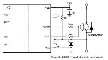
I would like to know the recommend value for the CA1 and CA2 , Rz of following circuit. (UCC5320 is S version)

(CA1 and CA2 is a decoupling capactor. There should be 0.1uF.?)

For E version, can we use the E version of UCC5320 wit the above S version circuit?

Regards,

Koji Hamamoto

  • Hi Koji,

    Yes, these are decoupling capacitors. TI recommends a value between 220-nF to 10-uF with an additional 100-nF capacitor in parallel for high frequency filtering.

    Yes, the E version can implement the negative bias with a zener diode as well.

    regards,
    Mateo
  • Hi Mateo,

    Thank you for your reply.
    How much is the Rx?

    >Yes, the E version can implement the negative bias with a zener diode as well.
    Is this meant that the E version can be used with the circuit of Fig 38?

    Regards,
    Koji Hamamoto.
  • Under this configuration, there will be a steady state power consumption from Rz.
    Therefore I would suggest finding a zener diode with a low Rz to lower the power consumption.

    Yes, but for the E version, the cathode of the Zener diode will be connected to GND2 along with the emitter of the IGBT.

    Regards,
    Mateo

  • Hi Meteo,

    Thank you for your reply.
    What is Rz you mentioned? Is that a series resistor or an operation resistor of zener?
    I understand that the operation resistor should be low. However the series resistor is depends on the load current.
    If the series resistor is small, the load current will be large. (This means the power consumption will be large.)

    How can we set the Rx value?(How can we calculate that value.)

    Regards,
    Koji Hamamoto

  • Hi Koji,

    In my last post I was referencing the internal resistance of the zener diode.
    For the series resistor, select a resistor that will limit the current to be less than the maximum reverse leakage current for the given zener voltage and to limit the power dissipation of the diode.
    These values can be found in the selected zener diode's datasheet.

    Regards,
    Mateo
  • Hi Mateo,

    I thought the resistor should be set to limit the current is more than the maximum reverse current. Because the zener should be flow some current to provide(or clamp) the zener voltage (Vz).

    Is my understanding incorrect?

    Regards,
    Koji Hamamoto
  • Hi Koji,

    Yes, you are correct.

    Looking at a generic zener diode's datasheet, the resistor should be selected to set the zener current as shown below:


    regards,
    Mateo