This thread has been locked.

If you have a related question, please click the "Ask a related question" button in the top right corner. The newly created question will be automatically linked to this question.

Looking for guidance on charging a USB-C host

Other Parts Discussed in Thread: TPS65982-EVM, TPS65983B, TPS65982, TPS65981

Hi,

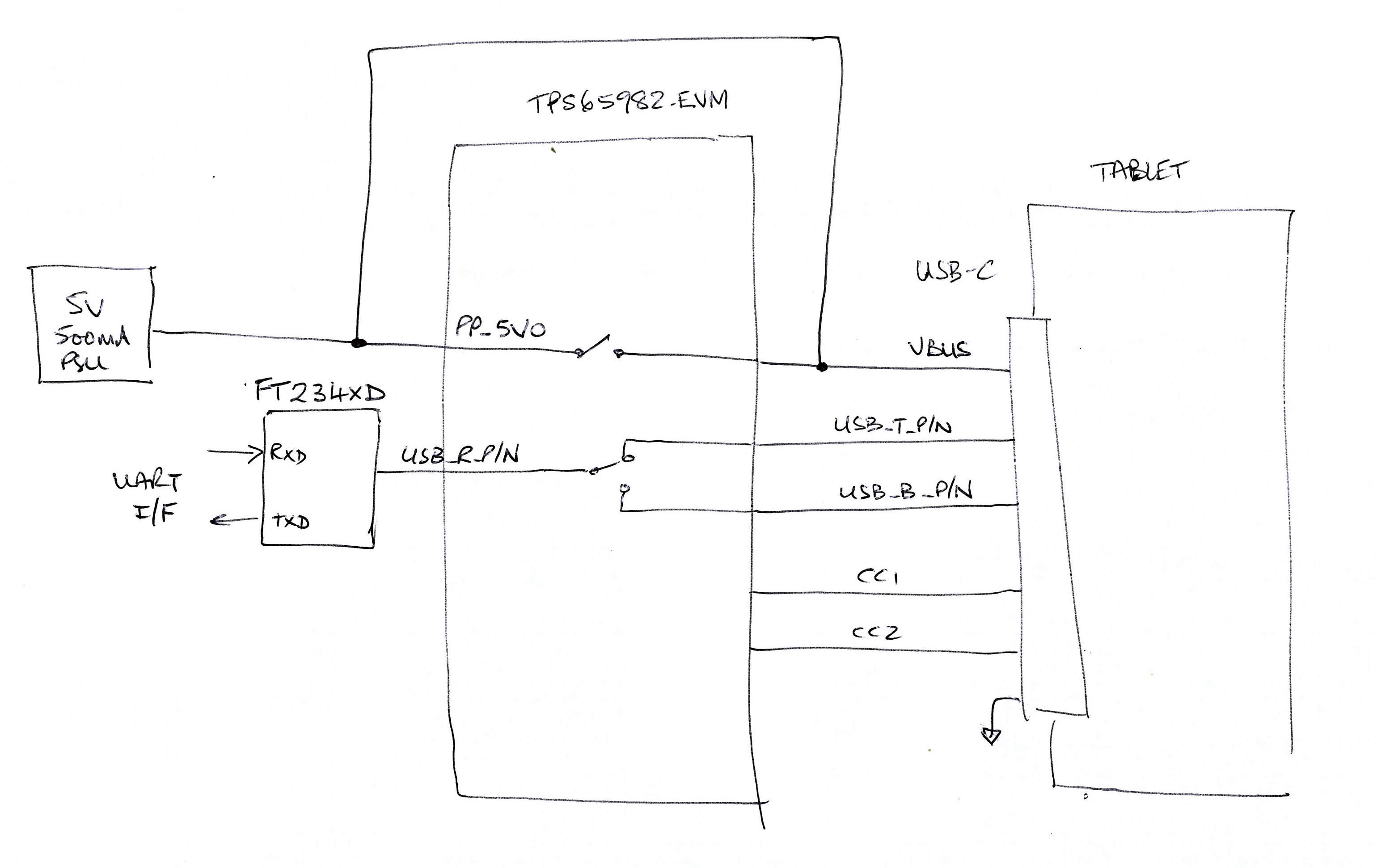
My customer has an existing UART bridge between to USB hosts, one of which is a tablet.

I have been tasked with adding a power solution to charge the tablet, assuming the tablet is USB-C.

I have been looking at the devices available from Texas Instruments, but being new to USB-C am having difficulty seeing which chips (if any) are intended for this purpose (as opposed, for example to being intented to go inside the tablet).

I would be grateful for any assistance in narrowing down which chips are suitable for the purpose.

Thank you.

Rob Strange

Design Engineer

  • Rob,

    The picture you are showing is a legacy USB connection where the power is limited to 500mA.

    If this is you intention, you can wire it according the the USB 2.0 Legacy connection requirements on page 65 of the USB Type-C Specification.

    If you need to expand you power capability, then we have many devices that will meet your needs.

    Regards,
    Chuck
  • Thanks.

    We do only want 5V 500mA.

    Do you mean that I can just connect the PC's VBUS to the Tablet VBUS?

    How does the tablet know that it is a USB data source (to the FTDI UART) but a power sink?  I thought there was some negotiation to be done to make that happen.

    I assume this is the diagram you are referring to (the page numbers vary between versions of the document):

    Regards,

    Rob

  • Rob,

    I was looking at my older 1.2 Version of the specification, so I sent you the wrong page.

    Take a look at section 3.5.2 USB Type-C to USB 2.0 Standard-A Cable Assembly. You can connect VBUS directly to 5V if you terminate the CC lines correctly to inform the UFP that you are a legacy 2.0 connection. The Type-C device will power up into 5Vsafe4p5to5p5V mode.

    Regards,
    Chuck
  • Thank you.

    I'm checking out those sections of the document now.

    (Specifically to understand how the C port knows it's a host, since I cannot connect the data lines as in that diagram - the FTDI chips are a pre-requisite).

    Thanks again,

    Rob

  • Hi,

    I've been trying to make the cable works as suggested, and it is not working.

    As far as I can see:
    1) we need a 56k resistor from CC to VBUS to enable 500mA charging
    but
    2) we need a 5.1k resistor from CC to GND to enable the tablet to connect to the FTDI chip as a host.

    If I use a 5.1k pulldown then the tablet communicates with the FTDI device.
    If I use a 56k pullup, the tablet will not connect to the FTDI device.

    If I use a 5.1k pulldown to get the FTDI connected, then remove it and replace with a 56k pullup to enable charging, the FTDI connection is dropped.

    I'm afraid this brings me back to the original question.
    How do I charge the tablet while also having the tablet as a data host?
    And do any of the chips in Texas's portfolio perform this function?

    Regards,
    Rob
  • Rob,

    To my knowledge, it is not allowed to have two downstream ports simultaneously in type-C.

    As you have tried above, you would have to have the tablet report as a UFP and the PC as a DFP to achieve charging and have to tablet enumerate as an appropriate data class to support the type of traffic you wish to generate. This enumeration across across your UART bridge appears to be your issue with getting this system to work.

    The USB to UART bridges would have to support the enumerated class of the tablet and correctly pass data between the UFP and DFP. I cannot speak to the capability of the FDTI part, so I cannot suggest how best to make this system work.
  • Hi Chuck,

    Many thanks for the reply.

    I do think this is perhaps overcomplicating things.  I included the PC to give an overview of the system, but it's not relevant to the design problem.  The FTDI chips separate the PC and Tablet USB buses, to they are oblivious to both being downsteam, since they are not connected to each other.

    Removing the PC, we just have a tablet charging and acting as a host at the same time.

    I'm not an expert on the USB-C spec, but the definitions of DRD and DRP certainly suggest it's possible.

    An application which I think exists is for a laptop docking station, where the USB C bus charges the laptop while allowing the laptop to be a host in the usual manner.

    I was hoping that one of the TI chips was designed to take the hard work out of making this happen.

    For example, we were wondering if the TPS65982-EVM would achieve this.  It supports many configurations including docking station, but we're not sure that's what we need.

    Best regards,

    Rob

  • Rob,

    I was trying to stay with legacy modes, but if you do want to use DRD, then you will require a full USB PD controller in the tablet. The best part for you to look at will be the TPS65983b. Here is a link to the part- www.ti.com/.../description.
  • Thanks

    This is a purchased Samsung tablet so I cannot modify its design.

    Assuming the tablet meets the USB-C spec, do you think the chip you suggested would also be suitable for using in the adapter that connects too the tablet?

    Regards,

    Rob

  • I also have the same application requirement which is to attach an FTDI USB-to-UART device (such as the FT232R) as a UFP to a tablet as DFP whilst at the same time charging the tablet @500mA.

    I have setup a TPS65982-EVM board as shown here:

    I have customized the EVM settings using the TPS6598X Application Customisation Tool as best I can. I can get the EVM board to correctly request the power role change to set the EVM as the source and tablet as a sink and can charge the tablet at the 5V 500mA level but the EVM seems to stay as a DFP. In experimenting with customisation settings I can sometimes get both charging and FTDI data connection but not reliably.

    Question for Chuck Branch,

    Can you suggest what the key customisation settings required are to get this to operate correctly and are the VBUS and USB connections I've made in the EVM board look sensible?

    Regards,

    Gerry

  • Gerry,

    The only change that I would make to your diagram is to not short from the 5V VBUS connection from the PSU to the VBUS connection on the Tablet. The TPS65982 is intended to be the power switch and it must be able to interrupt the power supply for your application. In your case, you would configure the '982 as a DFP port that can only supply 5V.

    Please let me know if you have any further questions.
  • Hi Chuck,

    Sorry, I made a silly mistake in the drawing, I meant to show the VBUS connected to the FTDI device like this:

    So what I want to do is configure the '982 as a sourcing UFP for connecting the FTDI device and supplying 5V power to the tablet and the tablet as a sinking DFP. It's the customization settings for achieving this that i seem to be having trouble with. Any guidance on settings would be much appreciated.

    Best regards,

    Gerry

  • Gerry,

    If I understand your requirement correctly, you are looking to perform a data role swap on the USB lines. This is possible, but it does not actually change the power role of the port, only the data role of the USB port.

    Is this what you want to do?

    Chuck
  • Hi Chuck,

    For the tablet, we want it to be a DFP (or host in USB2.0 terminology) and the FDTI/TPS65982 to only ever be a UFT (or device). My understanding is that a DFP will normally be a source of power so we would want the TPS65982 to request a power role swap so the tablet is a sink. I hope that makes sense?

    Regards,

    Gerry

  • Gerry,

    How does you FDTI device respond the the roll swap change in power supply? VBUS will be at least partially discharged as part of a roll swap. If your FDTI chip does not reboot fast enough, this could cause the intermittent issues you are describing.

    Regards,
    Chuck
  • Hi Chuck,

    Thanks for those comments. I'll check how the FTDI responds to the VBUS changing over. In the meantime, can you suggest what the key TPS65982 customisation settings should be for the FTDI/TPS65982 to a sourcing UFT?

    Best regards,

    Gerry

  • Hi Chuck,

    I have succeeded in customising the TPS65981-EVM to behave as required as defined in the sketch I posted on 1-Dec-2017 i.e. the TPS65981 acts as a device and makes a USB connection the FDTI device and also acts as a 5V source to charge the Tablet via the PP_5V0 power path.

    However, if the tablet battery is fully discharged, I can't find a way to customise the TPS65981 to start charging the tablet, the PP-5V0 power path never gets enabled. Can you suggest how this can be done?

    Regards,

    Gerry