This thread has been locked.

If you have a related question, please click the "Ask a related question" button in the top right corner. The newly created question will be automatically linked to this question.

DS90UB925Q-Q1: DS90UB925 / DS90UB926 used for repeater mode

Part Number: DS90UB925Q-Q1
Other Parts Discussed in Thread: DS90UB926Q-Q1

HI Sir 

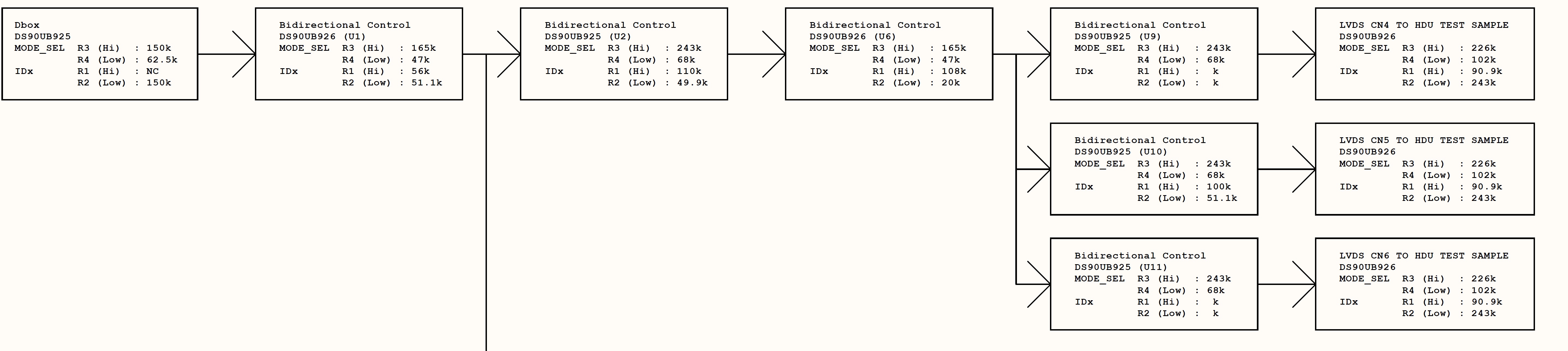
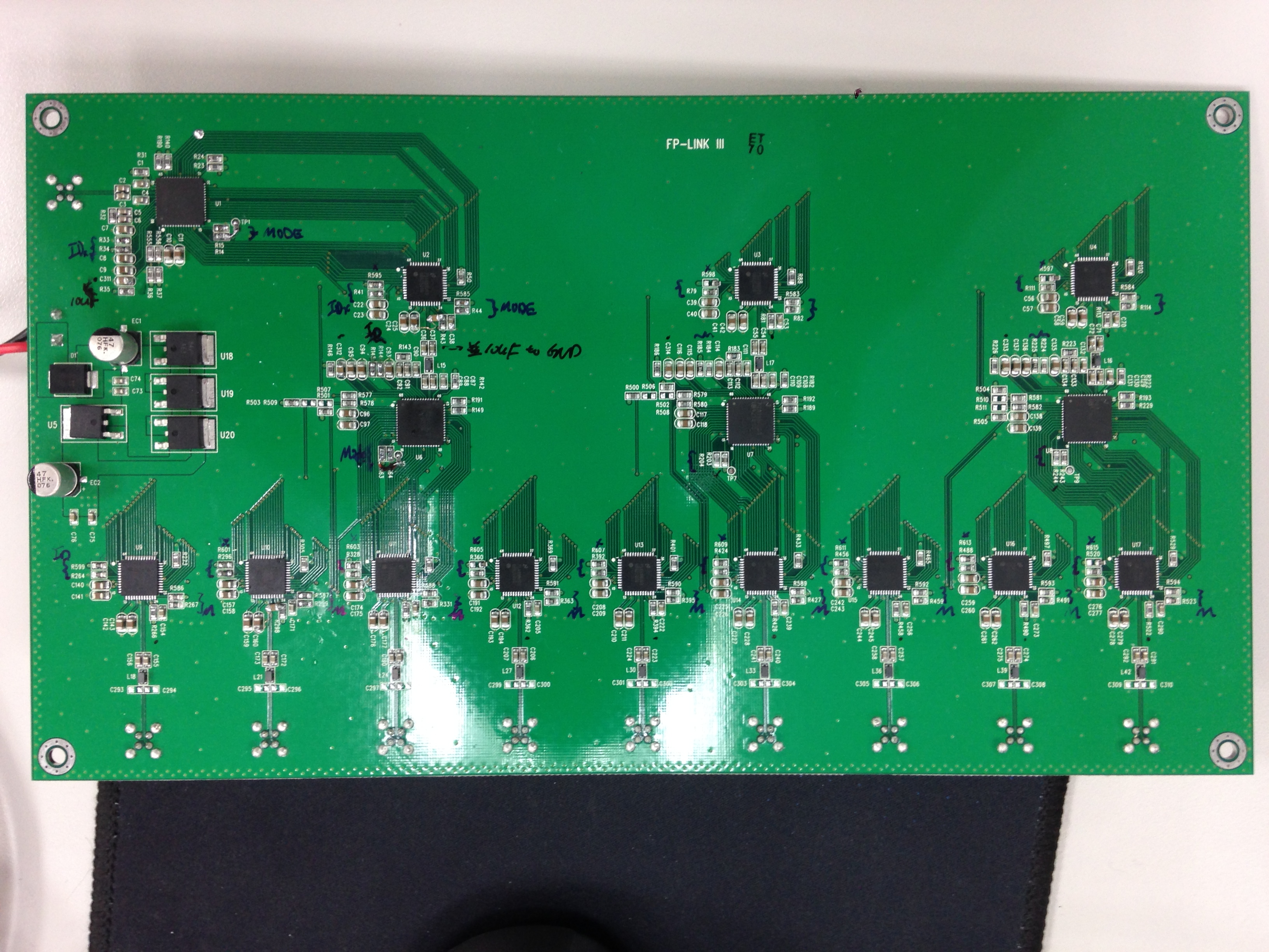
Below is our system block diagram and picture 

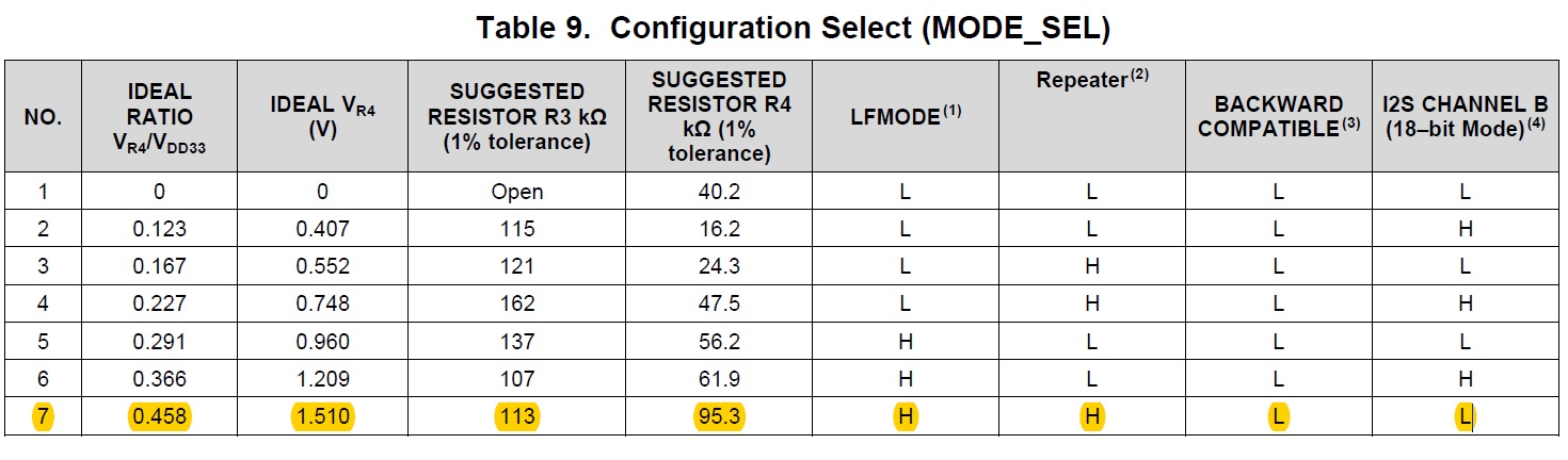
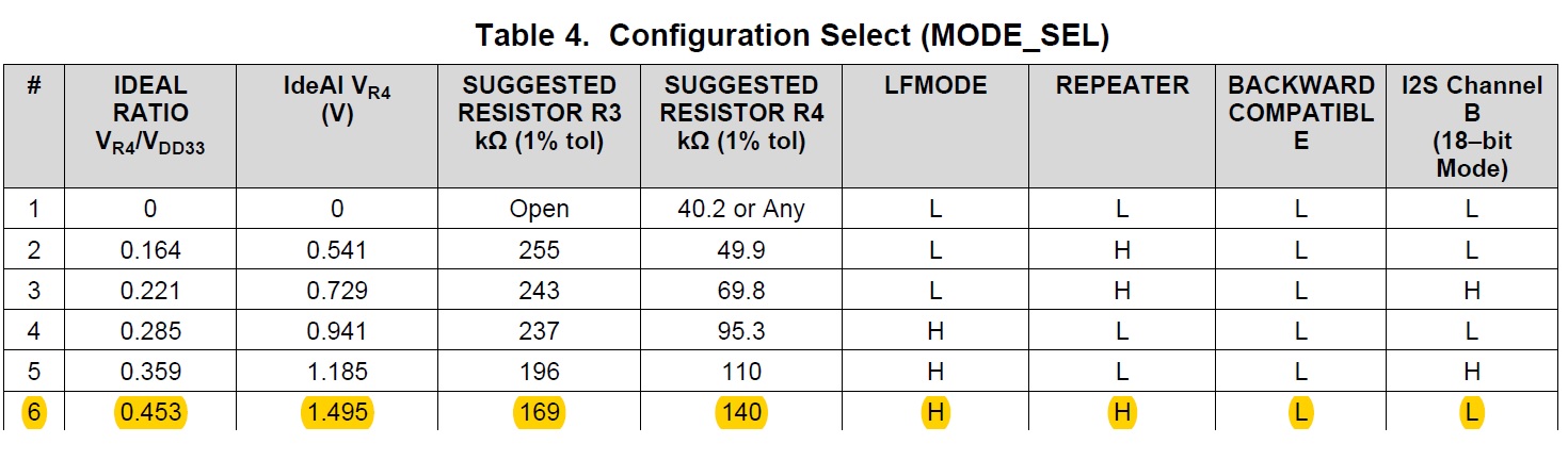
We setting DS90UB925/926 for repeater mode ,but so far can't display normally 

1. Do you have any suggestion for this issue 

2. You can see our structure is DS90UB925/926 on board without any cable ,do I need to turn on repeater mode ?

Thanks

  • Hi Shiao,
    1. can you check step by step? for example, can you try the left UB925 and UB926, does it work?
    2. For repeater mode, from the block diagram, the right UB926 to 3pcs UB925 should work at repeater mode. Please refer to d/s description page33/34, the I2C link can work?
    //////////////////////////////////////////
    8.4.4.1 Repeater Connections
    The Repeater requires the following connections between the Receiver and each Transmitter for Figure 22:
    1. Video Data – Connect PCLK, RGB and control signals (DE, VS, HS).
    2. I2C – Connect SCL and SDA signals. Both signals should be pulled up to VDD33 with 4.7-kΩ resistors.
    3. Audio – Connect I2S_CLK, I2S_WC, and I2S_DA signals.
    4. IDx pin – Each Transmitter and Receiver must have an unique I2C address.
    5. MODE_SEL pin – All Transmitter and Receiver must be set into the Repeater Mode.
    6. Interrupt pin– Connect DS90UB926Q-Q1 INTB_IN pin to DS90UB925Q-Q1 INTB pin. The signal must be
    pulled up to VDDIO.

    best regards,
    Steven