This thread has been locked.

If you have a related question, please click the "Ask a related question" button in the top right corner. The newly created question will be automatically linked to this question.

DS90UB953-Q1: Configuring DS90UB953/DS90UB954 for STP cable operation

Part Number: DS90UB953-Q1
Other Parts Discussed in Thread: DS90UB954-Q1,

Hello,

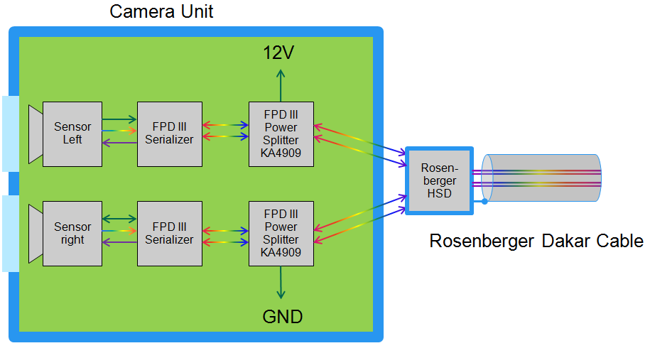
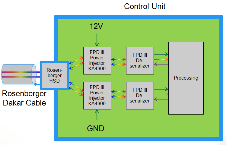
we designed a system that transfers sensor data via fpd link using serializer/deserializer pair DS90UB953/DS90UB954.

The chips are connected via STP cable and we want to use the full bandwith transferring full HD at 60fps.

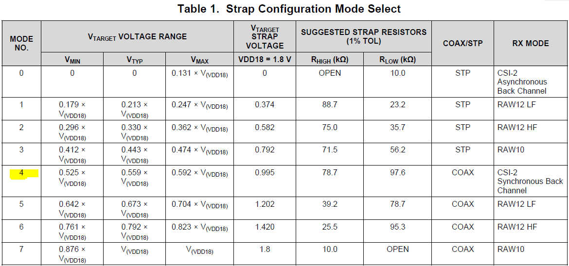
The IDX configuration of the serializer is set by hardware to IDX1 (I2C 8-Bit Address 0x30). I guess this is the COAX mode, as the system comes up with this mode after power up. Although we use an STP cable, the communication is working without errors at 30fps (half bandwith).

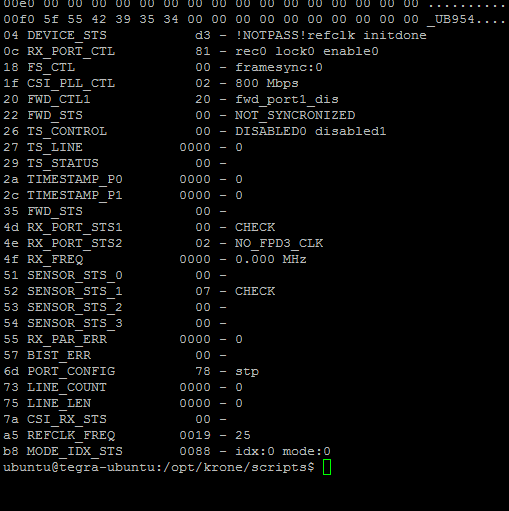
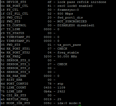
When we try to set the mode of both serializer and deserializer to STP (via I2C, the serializer first), the transmission looses look and there is no FPD3_CLK detected (see register settings below).

Is it possible to switch the cable mode in a running system? How can we set the IDX configuration to STP mode, there is no indication in the serializer datasheet (Table 8, page 21)?

Thanks and best regards,

Rolf

  • Hi Rolf,

    The register settings you provided did not show up on the post, could you please share them again?

    In terms of the current hardware setup:
    1) Ensure the 50Ω termination is removed on both DOUT- for DS90UB953 and RIN- for DS90UB954.
    2) What are the values of the coupling caps on DOUT± on the DS90UB953 and RIN± on the DS90UB954?
    3) Is there a POC network connected to DOUT± or RIN±?

    Regards,
    Mandeep Singh
  • Hi Mandeep,

    after switching the serializer to STP mode I get the following deserializer register settings:

    1) There is no external hardware termination, neither at DOUT- nor at RIN-.

    2) The values of the coupling caps are 15nF on RIN and 33nF on DOUT.

    3) There is a POC network that injects power at the deserializer by a coilcraft choke KA4909-AL.

    Although we are using STP cable we realized a transmission of data at 2Gbps over a length of 18m. We need to get a stable transmission of data at 4Gbps over a length of 11m.

    Regards,

    Rolf Casper

  • Hi Rolf,

    Are you providing power to the Deserializer over POC with STP? We recommend removing the POC network as it is not a supported feature with STP. Even if you are not using it to power the Deserializer, it can still cause issues to the transmission.

    Do you have any waveforms of the Back channel and Forward Channel?

    Regards,
    Mandeep

  • Hi Mandeep,

    to understand our requirements I'll try to explain the system architecture.

    The system consists of a stereo camera unit and a control unit. The stereo camera unit contains 2 sensors each connected to one serializer. The sensor data is transmitted to the control unit via a single shielded cable consisting of 2 twisted pairs using 4-pin rosenberger connectors. The control unit contains 2 deserializers, each of those receiving data from 1 serializer.

    The camera unit has to be powered remotely via the single fpd link cable. What we do is, we inject 12V power to one twisted pair at RIN of deserializer 1 and GND to the other twisted pair at deserializer 2 (see block diagrams below).

    As I understand your message, power over STP is not supported at all. So is there any way to transfer power and data via the same single cable?

    Regards,

    Rolf

  • Hi Rolf,

    By not supported, I meant to say we have not validated or tested the part for POC with STP. If I understood correctly, you are provding power to the serializer through both RIN+ and RIN- on one twisted pair and Ground on the other? If so, this would be the correct configuration. Issues occur if only RIN+ is being provided power and the RIN- is ground.

    I noticed the DS90UB954-Q1 register 0xB8 = 0x88, this suggests that you have the Deserializer set-up to accept an external clock but my understanding is that you are providing a 25MHz reference clock. Could you try Mode 4? CSI-2 Synchronous Back Channel and provide the register settings again.

    Reading through the earlier post again, I noticed that you are programming the serializer to put into STP. Typically, the hardware changes alone are sufficient to place the part into STP mode. Would you be able to provide the register settings of the DS90UB953-Q1 as well?

    Regards,

    Mandeep

  • Hi Mandeep,

    I changed the strap resistors  to mode 4, but there is no change.

    I get the following register settings:

    Serializer DS90UB953

    Deserializer DS90UB954

    The Serializer remains in COAX mode. As soon as I configure the serializer to STP mode (setting register 0x03 to 0x80), it is no longer accessible via I2C.

    Regards,

    Rolf

  • Hi Rolf,

    So you’re still not able to receive the data from the sensors? The registers are showing that you are receiving a valid LOCK.

    Register 0x03 will show COAX because you are in MODE 4; however, you can still transfer data in STP. Could you leave register 0x03 as default and check if you are receiving data?

    Regards,

    Mandeep Singh

  • Hi Mandeep,

    indeed I can receive data from the serializer with the changed settings. But I get the same behavior as with using COAX-Mode. With 2Gbps it is working with 15m cable length. With 4Gbps it is only working with a short cable (< 5m).

    The current settings are as follows:

    DU90SUB953:

    03 MODE_SEL             48 - syncmode forcemode COAX
    06 CSI_PLL_CTL        49f2 - m:9 n:242 h:4
    06 CSI_PLL_CTL        49f2 - refclk:37.190083
    20 ALARM_CSI_EN         00 -
    20 CSI_POL_SEL          00 - D0- D1- D2- D3- CLK-
    21 CSI_LP_POLARITY      00 - D0- D1- D2- D3- CLK-
    22 CSI_EN_HSRX          00 -
    23 CSI_EN_LPRX          00 -
    24 CSI_EN_RXTERM        00 -
    52 GENERAL_STATUS       45 - link hsplllock BCC_ERROR rxlock
    55 CRC_ERR_CNT1       0000 - 0
    5d CSI_ERR_STATUS       00 -
    5e CSI_ERR_DLANE01      00 -
    5f CSI_ERR_DLANE23      00 -
    60 CSI_ERR_CLK_LANE     00 -
    61 CSI_PKT_HDR_VC_ID    12 - virtch:0 dataid:18
    62 PKT_HDR_WC         0180 - 384
    64 CSI_ECC              05 - ECC:05

    DS90UB954:

    04 DEVICE_STS           df - lock pass refclk initdone  
    0c RX_PORT_CTL          81 - rec0 lock0 enable0
    18 FS_CTL               00 - framesync:0
    1f CSI_PLL_CTL          02 - 800 Mbps
    20 FWD_CTL1             20 - fwd_port1_dis
    22 FWD_STS              00 - NOT_SYNCRONIZED
    26 TS_CONTROL           00 - DISABLED0 disabled1
    27 TS_LINE            0000 - 0
    29 TS_STATUS            00 -
    2a TIMESTAMP_P0       0000 - 0
    2c TIMESTAMP_P1       0000 - 0
    35 FWD_STS              01 - tx_port_pass
    4d RX_PORT_STS1         07 - CHECK
    4e RX_PORT_STS2         04 - freq_stable
    4f RX_FREQ            6400 - 100.000 MHz
    51 SENSOR_STS_0         00 -
    52 SENSOR_STS_1         07 - CHECK
    53 SENSOR_STS_2         00 -
    54 SENSOR_STS_3         00 -
    55 RX_PAR_ERR         0000 - 0
    57 BIST_ERR             00 -
    6d PORT_CONFIG          78 - stp
    73 LINE_COUNT         0455 - 1109
    75 LINE_LEN           0b6a - 2922
    7a CSI_RX_STS           00 -
    a5 REFCLK_FREQ        0019 - 25
    b8 MODE_IDX_STS       008c - idx:0 mode:4

    How can I check if it's really a STP connection and what is the difference between COAX and STP concerning signal type or level? Can I detect the mode by measuring the signal with an oscilloscope?

    Regards,

    Rolf

  • Hi Rolf,

    I wanted to follow up with this thread. Good to hear that you were able to receive data with the changed settings. The datarate limit can be due to the attenuation of the signal over a 15m STQ.

    Yes, the signal levels for single-ended and differential is stated in the DS90UB953-Q1 Datasheet Electrical Characteristics (Section 6.5). You could detect the mode by probing the differential pairs to check the signal as both pairs will be transmitting the signal in STP mode.

    Regards,
    Mandeep Singh