This thread has been locked.

If you have a related question, please click the "Ask a related question" button in the top right corner. The newly created question will be automatically linked to this question.

DP83848I: DP83848I PHY interface

Part Number: DP83848I
Other Parts Discussed in Thread: DP83630

Dear Sir, please, answer

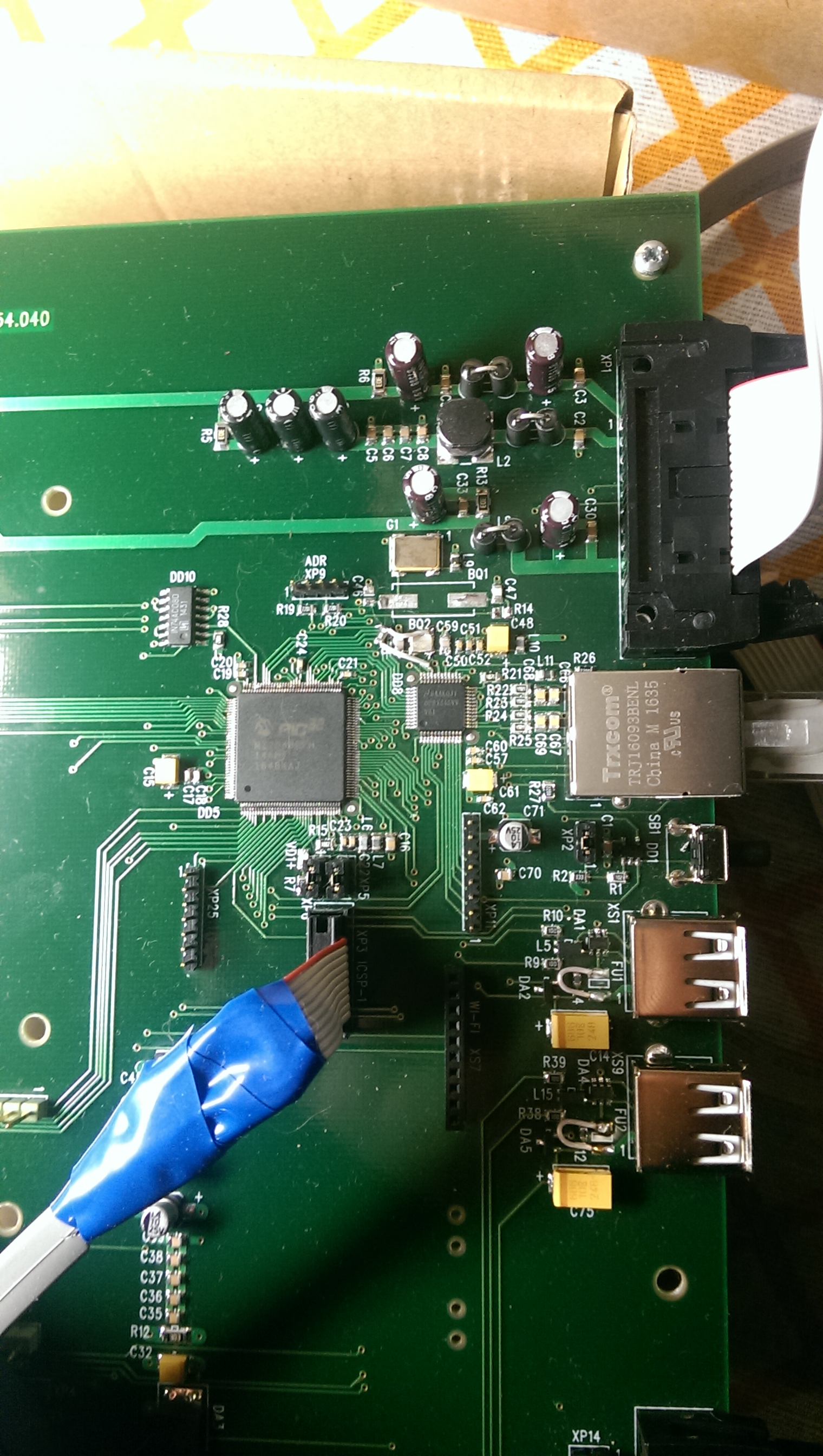
I use board (newly developed by us, four-layer PCB) with PIC32MZ2048EFH144-I/PH + DP83848iVV (MMI mode). POSC=12MHz.  And I tried FRC mode with Fppl = 200MHz.

Based on the project .......\Microchip\harmony\v2_04\apps\rtos\freertos\tcpip_client_server.

MAC driver>External PHY Configuration>External PHY type - National_DP83848.

 RMII flags - No checked.

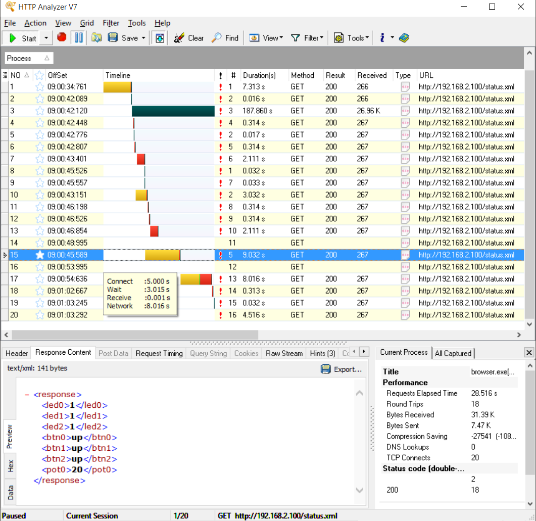
When WEB browser is connected, there are big delays when receiving data on the main page. I tested 10 Mbit/s and 100 Mbit/s - there is no particular difference.

Delays are always different. Previously, we were doing a module with PIC32MX + DP83630 - there was a two-layer board and 100 megabits/s did not work at all, but for 10 megabits/s everything worked without delays. I reason this way: if I connect a PC and PC sees, that the network is connected to 100 megabit/s, is it likely that with the connection of the transformer everything is good?

I use PIC32MZ starter kit too and it works well, without delays, but PIC32MZ starter kit has another transceiver installed.

As for the MII interface, it's unlikely I made a mistake in connecting the two chips.

Here is the data of the HTTP Analyzer, circuit, photo of the board, datasheet  on theTRJ16093BENL connector.

QUESTIONS:

1) Such delays may be due to poor layout of the elements on the board or is it likely a problem with the software driver? How do I find out the reason for the delays? May be, it is possible to create a test signal to test the signal through the transformer using an oscilloscope?

2) I do not know where to connect the contact P8 of the TRJ16093BENL. May be to "0 V" оf the my board - "0 V" is the common potencial of the board (but it hardly makes sense)?   "0 V" of my board  should not be earthed for safety reasons. 

I plan to connect to "earth" contact P8 of the TRJ16093BENL, but while it is not connected anywhere.

3) Where to connect metal case of the TRJ16093BENL ?

+++TRJ16093BENL__.pdf

DP83848.docx

TIA

Sincerely

Vladimir Naumenkov

www.agat.by

  • Hello Vladimir,

    Thank you for using the TI forum. Our product expert will get back to you by Tuesday.

  • Dear Mitch, thank you

    Sincerely,

    Vladimir Naumenkov

    www.agat.by

  • Dear Mitch, good morning

    Please, remind to your produсt expert  about me.

    TIA

    Sincerely

    Vladimir Naumenkov

    www.agat.by

  • Hi Vladimir,

    I see that the application uses TCP/IP. The delay in packet communication may be due to re-transmission of lost packets. Packet loss depends on both board design and software design. As first debug steps, can you check that RBIAS resistor is 1% tolerance? Also can you change R30 to 0ohms and re-test? Does the system have PRBS generator/checker in the MAC that can send random packets on MII interface?

    Connect the P8 and the metal jacket of connector to earth. If immunity is a concern, I would also recommend keeping earth plane and 0V plane physically separated by as much distance as possible on the system.

    -Regards,
    Aniruddha
  •  Dear Aniruddha, thank you

    1) We set R30=0 Ohm and it's much better. I have great doubts about the quality of the work of the generator with an external crystal. Maybe we just need to install an external generator 25 MHz?

    2) Please, see PSB design (see attach, page 1 and 2) in connection with the DP83848 to the transformer. I understand, that the location of the  C48, C50-C52, C57, C60-C62 on the board are idiotic - they do not do any good. But there is no place on the top side of the board. Probably it is necessary to put them on the bottom?

    3) I'm more interested in what you say about the location of the R22-R25, C66-C69 and  connection the DP83848 to the transformer?

    TIA

    Sincerely,

    Vladimir Naumenkov

    www.agat.by

    MP2-2.pdf

  • Hi Vladimir,

    Is there any way you can send us a scope shot of the MDI (cable interface side) when in forced 10Mbps and 100Mbps operation?
    I would like to see the link pulse of the 10Mbps signaling and the eye diagram of the 100Mbps signaling.
    Please use a 100 ohm termination for the capture.
    You can follow this debug app note for information regarding termination cables: www.ti.com/.../snla266.pdf

    To force 10Mbps: set register 0x0h to value 0x0100h
    To force 100Mbps: set register 0x0h to value 0x2100h

    Also, can you send an image of the RX_CLK to any of the RX data lines at the MAC as well as TX_CLK to any of the TX data lines at the PHY?

    Kind regards,
    Ross
  • Dear Ross, thank you

    I will do it a little later and send you oscillograms

    Sincerely

    Vladimir Naumenkov

    www.agat.by