This thread has been locked.

If you have a related question, please click the "Ask a related question" button in the top right corner. The newly created question will be automatically linked to this question.

THVD1500: RS485 communication is not normal

Part Number: THVD1500
Other Parts Discussed in Thread: SN75176B

Hi ,

     I used THVD1500 in a RS485 network.The node number is 14,baud rate is 250K.total cable length <15M.5V power supply.

But found one node which is nearest from the master is not normal.Others is ok.

1.Add 120 ohm termination,the communication is normal.

2.Without 120 ohm termination,Change the THVD1500 to SN75176,the RS 485communicaiton is ok.

3.Still use THVD1500,change the node number is below 7,without 120ohm termination,All the node commnication is normal.

question:1.is it necessary to add termination in this application?

               2.why SN75176 is ok without 120ohm termination?And the THVD1500 is not normal without 120ohm termination.

  • Kevin,

    Sorry to hear that. Can you give a little description on the network, like what's the topology, how long the stub is for the bad node, any termination on the bus? I know the problem can go away with termination. But do you mean adding termination for that node or for the whole bus?

    I assume you didn't have any termination on the bus. If that's the case, it would be recommended to add termination on both ends of the bus. The system may still work without any termination, but it depends on several factors, like data rate, cable length (stub length) and cable characteristics. In general, with no termination, there will be reflection on the bus from near end to far end. But if the speed is low (rise time is longer) and distance is short, the reflection time is negligible to the bit time, in which case the transmission may still be OK.

    Please provide more information, we take a deep look.

    Regards,

  • Hi Hao L:

        sorry for the delay of this case.And thanks for your support!

    1.Use bus topology.Limited 2ft for the stub from  the bad node.No termination on the bus.250kbps data rate.

    2.I added the termination on the end of the bus,can solve the issue.

    3.THVD1500 tr is 250ns,and SN75176B is 20ns.if according to equation 2Tpd<1/5Tr,2ft stub,asssume that SN75176 can cause the signal reflection but

        THVD1500 not.But actually,THVD1500 cause the reflection but SN75176 not.I want to know the reason.

        remark:Tpd :Signal propagation time

    Thank you very much again for your great support.


  • Kevin,
    I agree it looks like SN75176B would create more reflection than THVD1500. Is it possible to capture/compare the signal waveform at the receiver end? Another place to look at is the receiver. The Vit of these two devices are set differently. I'm not sure how much the impact would be though.
    Regards,
    Hao
  • Dear Hao L:

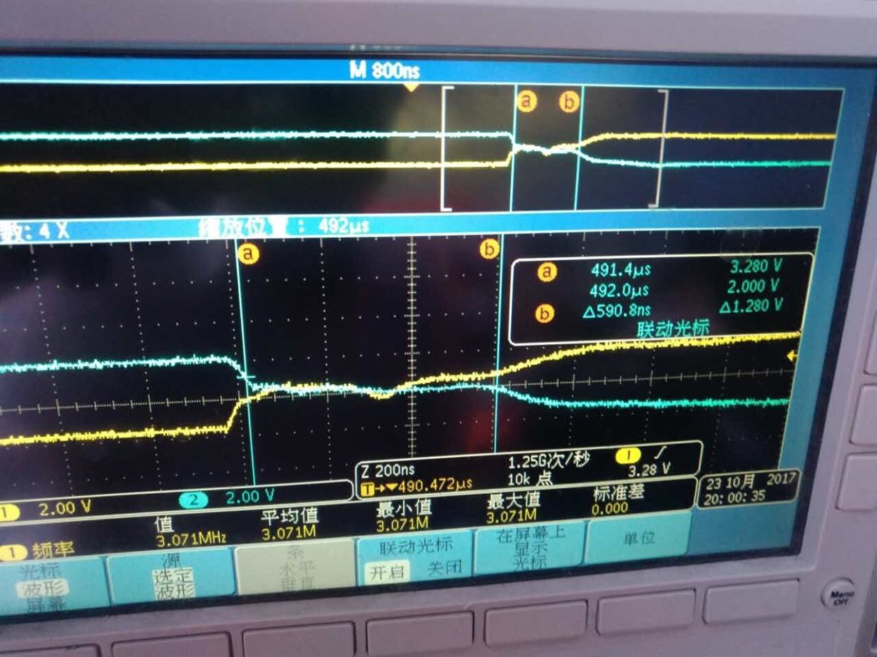
        sorry for delay reply and thanks for your support on this case.Below is the receiver end signal waveform.

  • Kevin,
    1) Is the waveform from THVD1500 or SN75176B? Is it possible to compare the waveforms of both devices?
    2) Do you plan to add termination or do you have to live without it?
    3) Can you tell me one more time specifically the reason that how the communication failed? Were there missing bits due to the abnormal rise time?
    Regards,
    Hao
  • Hi Hao L:

     1.This waveform is from THVD1500.This waveform is not correct,Va-b is near 0,below 200mV.And the SN75176 Va-b waveform is good .

    2.This waveform is tested without the termination.If adding the termination ,the waveform will be good.

    3.The receiver end of THVD1500 is near 0,below 200mV,abnormal.Communication fialed.

    thanks.

  • Hi Kevin,

    (Hao is on vacation today, so I can try to help out.)

    Thanks for helping to clarify the images. This waveform looks very strange to me; I wouldn't expect for the A and the B lines to stay at the same voltage like this unless the driver were disabled.

    Is it possible that the bus is idle (undriven) during this waveform (i.e., in the period marked between the two cursors where the differential level is close to 0 V)? Or, is it possible that multiple nodes are transmitting simultaneously during this period? In either case it is possible for the differential voltage to become close to 0 V. You could confirm whether or not this is the case by observing the "DE" control signals on the oscilloscope at the same time as the A/B signal waveforms.

    The reason I bring this up is that the enable/disable times are a little different between the THVD1500 and SN75176B, so they may need different wait times when transitioning between transmit and receive modes. They also may behave differently when disabled; each one will be high impedance, but there may be slight differences in high-side versus low-side leakage currents that could affect the voltage on the bus during idle conditions. Again, checking the DE control signals would be the best way to see if these factors are responsible for the differences you are observing.

    Regards,
    Max
  • Hi Kevin,

    I just wanted to check in on this again - were you able to resolve these issues?

    Thanks,
    Max