This thread has been locked.

If you have a related question, please click the "Ask a related question" button in the top right corner. The newly created question will be automatically linked to this question.

DS100DF410: eye diagram, phase offset, strange things

Part Number: DS100DF410
Other Parts Discussed in Thread: USB2ANY

Hi,

we have a problem using the DS100DF410. When we temperature cycle the board, sometimes get CRCs on the serdes link.

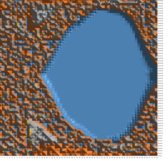
1) After getting an eye measurements during this, we have seen, that there's a phase offset which changes with temperature.

Is this a normal thing? See attached image.

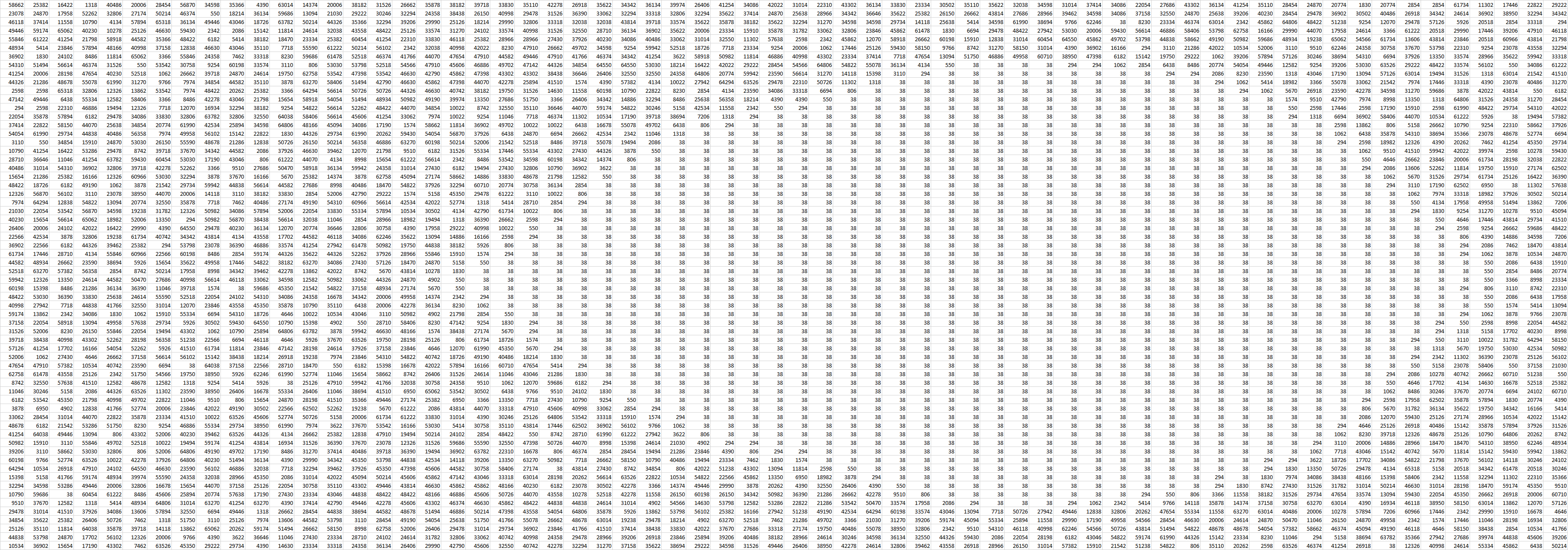
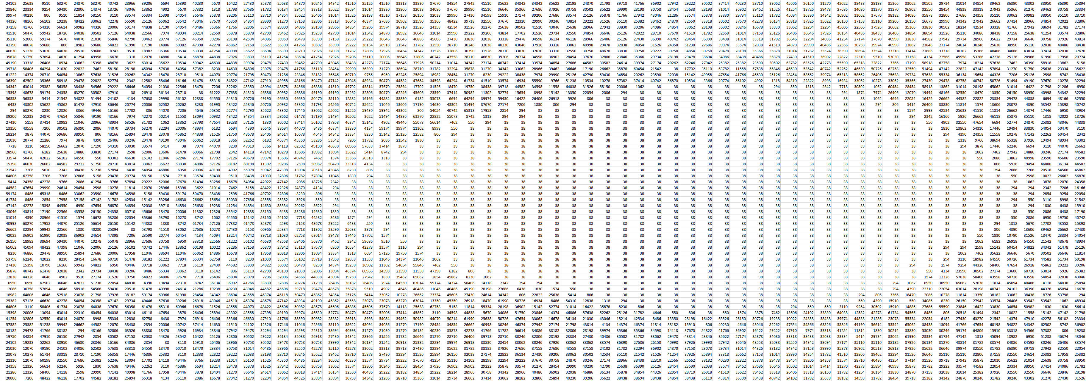
2) Also the eye diagram is not 0 in the center, but a constant nonzero number, what is the reason for that? See excel below.

3) After changing the vertical range from +-100mV to +-400mV, the eye did not change so much, it seemed like +-150mV or so. See the two excel table below.

please help us out with this ,

regards,

Lorand

  • These results are not normal. It would be useful if you could provide the values you are observing for retimer channel registers 0x03, 0x27, and 0x28 both before and after CRC errors are observed.

    I've included below for ease of reference our recommended procedure for configuring the retimer for plotting the eye diagram. By the way, have you tried using TI's SigCon Architect GUI software. This GUI implements a functional tab that plots retimer eye diagrams for you.

    Plotting an Eye Diagram

    The Eye Opening Monitor is capable of plotting an equalized, but non-retimed eye to represent the quality of signal that is going into the CDR block. This feature is useful for diagnosing gross signal integrity errors. The eye plot generated by the EOM cannot be used to extrapolate performance to bit error rates beyond 1e-7.

    The EOM generates the eye plot according to a 64 x 64 matrix. Each grid space in the matrix consists of a 16-bit word that represents the number of times the incoming data stream touches that particular phase and voltage level. The EOM under-samples the incoming data stream by recording the total hit count for each combination of phase and voltage, one grid space at a time.

    To configure the EOM to plot the eye diagram, sometimes called fast eye capture, use the following registers.

    Step

    Register[bits]

    Value

    Description

    1

    0x3E[7]

    0

    Disable lock EOM lock monitoring

    2

    0x2C[6]

    0x11[7:6]

    0

    2’b xx

    Set the desired EOM vertical range as 2’b xx

    3

    0x11[5]

    0

    Power on the EOM

    4

    0x24[7]

    1

    Enable fast EOM

    5

    0x24[0]

    0x25

    0x26

    1

    When 24[0]   is 1 begin read out of the 64 x 64 array, discard first 4 bytes
    This bit is self-clearing.

    6

    0x24[0]

    0x25

    0x26

    1

    Continue reading information until the 64 x 64 array is complete.

    7

    0x3E[7]

    0x2C[6]

    0x11[5]

    0x24[7]

    1

    1

    1

    0

    Return the EOM to its original state. Undo steps 1-4

    The data recorded from the Eye Opening Monitor (EOM) begins at (X, Y) position (0, 0) and proceeds to position (0, 63). Next, the Y-value is reset to 0 and the X-value is incremented. This process is repeated until the entire 64 x 64 matrix is read out.


    Cordially,

    Rodrigo Natal

    HSSC Applications Engineer

  • Hi,

    here are the values you've requested:

    CH0,0x03=0x0C
    CH0,0x27=0x2C
    CH0,0x28=0x93

    CH1,0x03=0x40
    CH1,0x27=0x2C
    CH1,0x28=0x96

    CH2,0x03=0x40
    CH2,0x27=0x2C
    CH2,0x28=0x96

    CH3,0x03=0x41
    CH3,0x27=0x2A
    CH3,0x28=0x9C
    We had CRC on CH1

    The values did not change after the CRC errors.

  • Have you tried Rx adapt mode 2. This mode is enabled with the following settings:

    0x31 = 0x40

    0x1E = 0xE1

    CDR reset and release is recommended after these operations,

    0x0A = 0x1C -> asserts CDR reset

    0x0A = 0x10 -> releases CDR reset

    Cordially,

    Rodrigo Natal

    HSCC applications engineer

  • 1) We have tried this and did not really see any difference.

    2) Meanwhile we have tried to set our link to 1G instead of the 10G and got a new eye diagram.

    Does this look okay to you?

    3) Also We have tried to use the SigCon Architect, but we don't have the USB2ANY so it seems to be useless in this case.

  • Thanks. What are th voltage output differential, post-cursor and pre-cursor settings being used for the Tx link partner to the retimer Rx?
  • Hello,

    meanwhile we did not have time to work with this issue, but now we are back at it.

    We use a different setup now, a samtec firefly optical cable. The optical receiver is 1.5cm from this retimer. When we look at the eye data, which we have read out via our processor and imported to excel (Don't have the USB dongle to use the SigCon Architect GUI software).

    The data is not 0 in the middle of the eye. Is this normal?

    Please see it below:

  • It is not normal. You should see zero hits at the center of the eye if everything was configured/executed properly.

    Cordially,

    Rodrigo Natal

    HSCC Applications Engineer

  • Hi,

    we have the transmitter from the firefly optical receiver 15mm-s from the DS100DF410 input. The link speed is 10.3125Gbps. Should we change any register on the retimer at all, or it should just work with the default? :)

    We don't have CRC-s on room temperature, but we've seen it before, that when having an eye exported like the one above, with non 0 middle, in the temperature chamber it'll not be error free. This may be a coincidence though.

    thanks,
    regards,
    Lorand.
  • It could just be in the spreadsheet.  The numbers are pretty consistent.  The retimer would not lock without an eye opening.

    What do you get for readings in the HEO and VEO registers 0x27 and 0x28?

    Regards,

    Lee 

  • Register 0x27 and 0x28 reads:
    0x27: 0x31
    0x28: 0x56

    We noticed something today.
    Scenario1:
    - Setup registers 0x3E, 0x2C, 0x11, 0x2A, 0x22
    - Set bit 7 and 0 in register 0x24
    - Get the 64x64 array of eye values.
    We see non-zero values in the middle of the eye.

    Scenario2:
    - Setup registers 0x3E, 0x2C, 0x11, 0x2A, 0x22
    - Write 0x1C followed by 0x10 to register 0x0A to reset CDR
    - Set bit 7 and 0 in register 0x24
    - Get the 64x64 array of eye values.
    We see non-zero values in the middle of the eye.

    Scenario3:
    - Setup registers 0x3E, 0x2C, 0x11, 0x2A, 0x22
    - Set bit 7 and 0 in register 0x24
    - Write 0x1C followed by 0x10 to register 0x0A to reset CDR
    - Get the 64x64 array of eye values.
    All values in the middle of the eye are 0.


    Finally a question from the datasheet. From the DS100DF410 DS section 7.5.13:
    "Register 0x22, bit 7, the eom_ov bit, should be cleared in this mode."
    By reading the description in the table for register 0x22.7:
    1: Override enable for EOM manual control
    0: Normal operation
    It seems that Section 7.5.13 says it should be cleared and the table it should be set. Which one is it?

    When we set this bit to 7 while doing the eye capture, we don't see an eye at all.
  • Any comments on this?

    thank you,
    regards
  • Finally a question from the datasheet. From the DS100DF410 DS section 7.5.13:
    "Register 0x22, bit 7, the eom_ov bit, should be cleared in this mode."
    By reading the description in the table for register 0x22.7:
    1: Override enable for EOM manual control
    0: Normal operation
    It seems that Section 7.5.13 says it should be cleared and the table it should be set. Which one is it?

    When we set this bit to 7 while doing the eye capture, we don't see an eye at all

    To recap, below is our recommended sequence for DS1xxDF410 parts,

    To configure the EOM to plot the eye diagram, sometimes called fast eye capture, use the following registers.

    Step

    Register[bits]

    Value

    Description

    1

    0x3E[7]

    0

    Disable lock EOM lock monitoring

    2

    0x2C[6]

    0x11[7:6]

    0

    2’b xx

    Set the desired EOM vertical range as 2’b xx

    3

    0x11[5]

    0

    Power on the EOM

    4

    0x24[7]

    1

    Enable fast EOM

    5

    0x24[0]

    0x25

    0x26

    1

    When 24[0]   is 1 begin read out of the 64 x 64 array, discard first 4 bytes
    This bit is self-clearing.

    6

    0x24[0]

    0x25

    0x26

    1

    Continue reading information until the 64 x 64 array is complete.

    7

    0x3E[7]

    0x2C[6]

    0x11[5]

    0x24[7]

    1

    1

    1

    0

    Return the EOM to its original state. Undo steps 1-4


     The data recorded from the Eye Opening Monitor (EOM) begins at (X, Y) position (0, 0) and proceeds to position (0, 63). Next, the Y-value is reset to 0 and the X-value is incremented. This process is repeated until the entire 64 x 64 matrix is read out.