This thread has been locked.

If you have a related question, please click the "Ask a related question" button in the top right corner. The newly created question will be automatically linked to this question.

TPS65986: Sleep control register questions

Part Number: TPS65986

Hi,

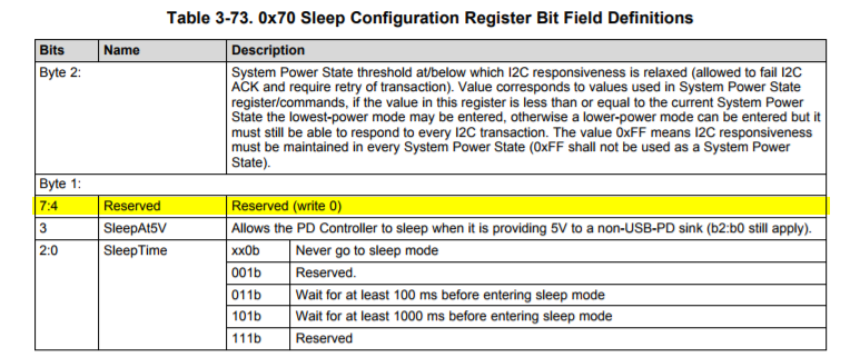
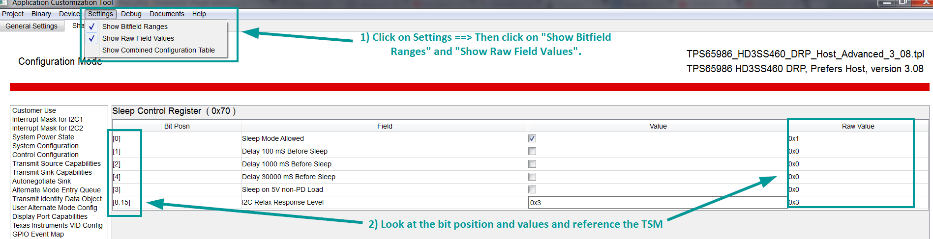
Can we combine the values of the sleep time register? I notice they are check boxes vs a drop down menu. 

I also see an option for 30s delay, but that is not on the TRM. Is it safe to assume that 30 second delay is the 111b (reserved)?

If we dont check any of the boxes, I assume it will default to 001b. What does this translate to in terms of delay seconds?

Also, is the "System Power State" (0x20) register just a user-chosen value? Say, we wanted to have IDLE mode with I2C active. Could we just set the System power state to a higher state than the Sleep Configuration register?

Thanks,

Josh

  • Hi JoFu,

    These are excellent questions. Look below for my comments/feedback to your questions in red:

    1) Can we combine the values of the sleep time register? I notice they are check boxes vs a drop-down menu.

    Unfortunately, no we cannot combine the sleep time delays. I would recommend choosing one of the checkboxes. If multiple boxes are selected, the GUI will configure firmware to the highest sleep delay value checked.  

    2) I also see an option for 30s delay, but that is not on the TRM. Is it safe to assume that 30 second delay is the 111b (reserved)?

    Good catch. The TRM will probably need to be updated to show this. The 111b isn't reserved for this. bit value 4 is (look below):

    3) If we dont check any of the boxes, I assume it will default to 001b. What does this translate to in terms of delay seconds?

    If you don't check any of the boxes, it will go to 000b. This means sleep mode is disabled. If the customer were to check ONLY the "Sleep Mode Allowed" box (001b), then sleep mode is enabled but without any time delay. 

    4) Also, is the "System Power State" (0x20) register just a user-chosen value? Say, we wanted to have IDLE mode with I2C active. Could we just set the System power state to a higher state than the Sleep Configuration register?

    In short, No it doesn't trump the sleep register. Both the System power state and the sleep register state would need to be configured for sleep mode allowed in order for the PD controller to go to sleep. If the system power state is set to go to sleep, but the sleep register is not set for sleep mode, then the PD controller will stay awake and active. Usually one would configure the sleep register once at the beginning, and then control the sleep modes through the System Power state (0x20). You can find information on the System Power States from this following webpage: https://msdn.microsoft.com/en-us/library/windows/desktop/aa373229(v=vs.85).aspx

    Also, I would recommend setting the GUI tool to show the bit values. This will help when referencing the TRM for bit values (look below). I hope this helps :-)


  • Thanks Aramis,

    Few follow up questions:
    -Is the 30s delay timer recommended? Bit 4 is under reserved and not explicitly labelled on the TRM so I wasn't sure.

    -Can you clarify the power states a bit more?
    In SLVUAH7B section 5.3, the power states say they go all the way down to S254 (0xFE). But in SLVUAN1A table 1-1 (and the GUI), System Power State can only be 0x0, 0x3, and 0x5. Just wondering if I can actually use all these power states in 0x70 and 0x20, or do we only allow 0,3, and 5.

    Thanks,
    Josh
  • Hi Josh,

    I'm always happy to help. Look below for my answers to your question in red:

    5) Is the 30s delay timer recommended? Bit 4 is under reserved and not explicitly labeled on the TRM so I wasn't sure.

    We recommend the 1000ms. The 30sec delay timer is primarily used for debugging purposes, and I believe that's why it isn't listed in the TRM. 

    6)Can you clarify the power states a bit more?

    In SLVUAH7B section 5.3, the power states say they go all the way down to S254 (0xFE). But in SLVUAN1A table 1-1 (and the GUI), System Power State can only be 0x0, 0x3, and 0x5. Just wondering if I can actually use all these power states in 0x70 and 0x20, or do we only allow 0,3, and 5.

    This is a good question. The power states are defined by Microsoft and Intel. Currently, there are 6 power states (S0 through S5), and S1-3 are basically the same power state with S3 consuming the least power in that state. The SLVUAN1A document is correct. The SLVUAH7B note can be confusing. The 0x20 register is 8 bits long and hence why it states you can write 0x00 to 0xFE. I would reference the Microsoft documentation for the latest power state levels: https://msdn.microsoft.com/en-us/library/windows/desktop/aa373229(v=vs.85).aspx