This thread has been locked.

If you have a related question, please click the "Ask a related question" button in the top right corner. The newly created question will be automatically linked to this question.

DS90C387: Using DS90C387 for Full HD display connection.

Part Number: DS90C387
Other Parts Discussed in Thread: DS90CF388

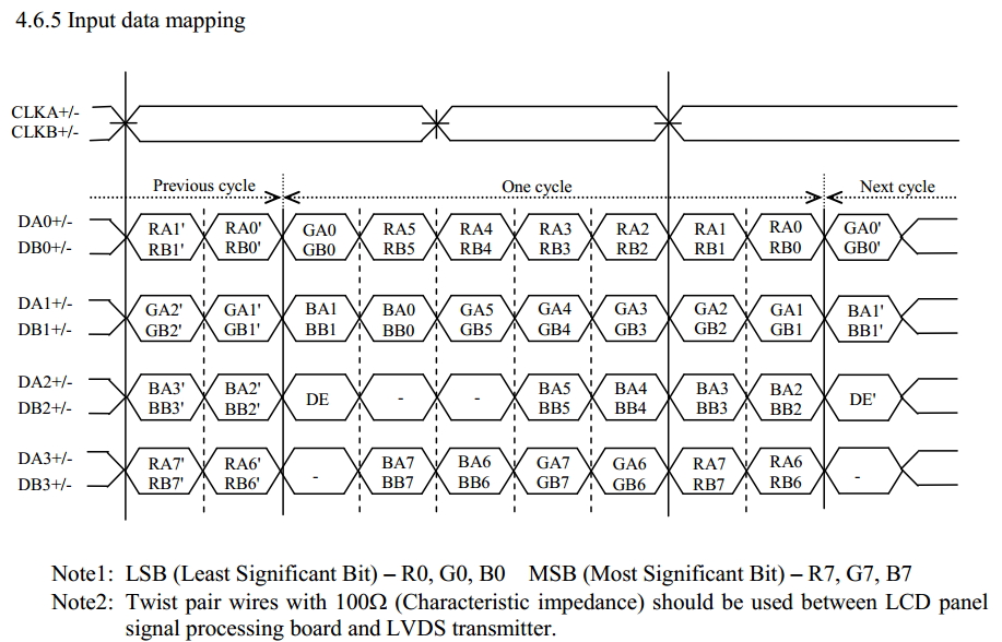
Hi, we are looking at using AM5728 work with DS90C387 to  display on one Full HD LCD(1920*1080). Since the pixel counts is huge, The LCD requires 2 port LVDS for odd pixel and even pixel transmission in same time. The data mapping requirment is showed in attach.

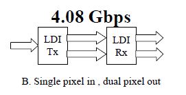
We are wondering if DS90C387 is configured in SINGLE TO DUAL PIXEL mode,AM5728 use one LCD buffer, like LCD1 to output 24 bit RGB continously in which containing odd and even pixel data, then DS90C387 split them to 2 LVDS port, one for odd pixel, another for even pixel? Does that workable? If yes,  what's the pixel clock(output from AM5728) relationship with LVDS clk(output from DS90C387 )?

How is DS90C387 able to recognize odd and even pixel data when it is splitting?

Thanks.

  •  

    Hi,


    Can you send the LCD display datasheet? What is the frame rate? Is this input data mapping for LCD input spec? I'm anticipate no issue because DS90C387 supports QXGA.


    What is your receiver IC spec on the LCD side?


    To program single to dual mode, In this mode data can be clocked into the transmitter at a maximum pixel clock frequency of 170MHz, table 4 on page 16 has SINGLE PIXEL PER CLOCK INPUT-TO-DUAL PIXEL PER CLOCK OUTPUT DATA MAPPING.


    To better assist with your design, can you send out the system block diagram?


    Regards,

    Dennis

  • Yes, that data mapping is from LCD datasheet. The LCD LVDS clk typical freq is 74.125MHz, resolution 1920*1080, with 24bit RGB per pixel.

    The system block diagram is like processor AM572x connected to DS90CF387, then go out of the main board to LCD, there should be a receiver on LCD, but I haven't got the receiver PN yet, but assume it should be working in a similar behavior as DS90CF388.  

    From the table 4, it seems DS90CF388 is able to split the odd and even data from what DS90CF387 has transmitted. Thus, I am curious to know how DS90CF388 recognize the odd or even pixel? in another way to ask, how should AM572x arrange the odd and even data into one LCD channel(a 24bit parallel bus)? Is that a feasible/common application design?

  • Hi,

    The design is single to dual pixel so DS90CF387 splits the old and even data from AM572x. The DS90CF388 is taking the dual LVDS ports, just like the data mapping you are sharing. For instance on table 4, TX pin R16 is mapping to RO0 and RE0 at TFT panel data signals. RO0 and RE0 are represent odd and even R0 signals.

    Your LCD is running at 75MHz at dual pixel mode. That means DS90CF387 is running at double frequency of 75MHz at 150MHz. The DS90CF387 freq is 65MHz to 170MHz on single to dual pixel mode. You need to make sure AM572x can support 150MHz to the TX.

    Can you send me your block diagram? What is your end application?

    If you would like to review and discuss with me on the phone, let me know and I will arrange it.  Also you can arrange it with your TI field apps in the region.

    Regards,

    Dennis