This thread has been locked.

If you have a related question, please click the "Ask a related question" button in the top right corner. The newly created question will be automatically linked to this question.

TCA9544A: General Question about the useage

Part Number: TCA9544A

Hello,

I'm totally new here and a bit lost, so please apologize if I may ask something very obvious or if this question was already asked.

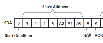
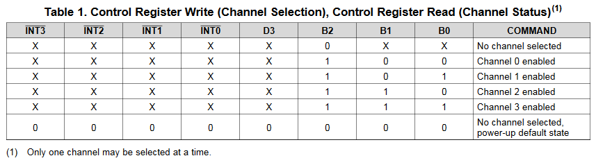
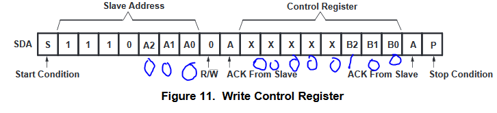
I want to use the TCA9544A as a switch between four identical light sensors with the same I2C address. But I do not understand completely how it woks. I have to use a ATmega328p as Master.

First I have to enable the channel with the address out of the data sheet right? And what must I do afterwards to communicate with my slave? Can I just send the I2C command with the slave address? Or do I have to pay attention of anything else?

Are there any examples where I can see how the communication works?

Thank you a lot for your help

Philipp

  • Hello Phillipp,

    “I'm totally new here and a bit lost, so please apologize if I may ask something very obvious or if this question was already asked.”

    -No need to apologize! This forum was made so people who aren’t as familiar with I2C and our products to can openly ask and get answers from others who may have years of experience in the topic.

    ---------------------------------------------------------------------------------------------------------------------------------------------------------------------------------------------------------------------

    “I have to use an ATmega328p as Master.”

    -It will be important for you to use the I2C ports on this mcu, using GPIO pins which may use a push-pull architecture could affect Vol readings as well as damage the devices communicating. You will need pins that utilize open drain architecture. Your mcu should have dedicated I2C pins for this.

    ---------------------------------------------------------------------------------------------------------------------------------------------------------------------------------------------------------------------

    “First I have to enable the channel with the address out of the data sheet right”

    -The TCA9544A has a programmable address. The address will depend on what you connected pins a0, a1, and a2 to.

    The address of the device assuming a0, a1, and a2 are tied to GND will be:111 0000 or 0x70h

    If a0, a1, and a2 are tied to Vcc with a pull up resistor: 111 0111 or 0x77h

    The last bit is R/W which if 1 will be a read, and 0 will be a write. You will want to use 0 to first write to the register.

    Once a start condition has been initiated, you send the slave address with the R/W bit. If the slave address is correct, you should see the TCA9544A pull down on SDA line signifying an ACK bit after the R/W bit is sent. This will tell you the device has gotten the message you've sent.

    ---------------------------------------------------------------------------------------------------------------------------------------------------------------------------------------------------------------------

    "And what must I do afterwards to communicate with my slave? Can I just send the I2C command with the slave address? Or do I have to pay attention of anything else?"

    After you have received an ACK from the device, you will need to send a byte of data to the control register of the TCA9544A to turn on the channels you need.

    In the table above, you do not care about the INT bits as you are writing and not reading. D3 is also a don't care term. B0, B1, and B2 are the only bits you care about. This device allows you to turn on only one channel at a time, which in your case is what we want. Also, at start up all channels are off. Lets say you want to turn on Channel 0.....

    You can send the following byte, 0000 0100 or 0x04h to select ch0

    Alternatively, you could send 1111 1100 or 0xFCh and still turn on ch0. As long as you don't mess with the two LSB and have bit 3 a 1, Ch0 will be selected.

    You should get an ACK after the last bit and then you can initiate a stop condition.

    The above example shows a full write command to the TCA9544A. The addressing bits are all pulled to GND shown by the zero bits on a2, a1, a0. The control register is written to as 0x04h. Afterwards the stop condition is initiated, which turns on ch0.

    From here you can re initiate a start condition and talk to the light sensor on ch0.

    After you get all the data you need to, you can initiate a stop condition and then start again and talk to TCA9544A by sending the address bits and R/W bit. After an ACK, you can write to the control register again and send 0000 0101 or 0x05h. Get an ACK then initiate a stop condition to activate ch1.

    From here just rinse and repeat.

    I hope this helps!

    -Bobby

  • Thank you so much for this awsome and detailde explination Bobby! That helps me a lot.

    I have also an other question about the voltage levels. My Microcontroller has a 5V level, and the light senors have 3.3V. I read in the Datasheet that I can use the TCA9544A as a level shifter. Do I have to send something to get this shift or does the chip this automaticly?


    Thank you

    Philipp
  • Hey Phillipp,

    "Do I have to send something to get this shift or does the chip this automaticly?"
    -You don't have to do anything, tying a pull up resistor between the channel output and your sensor to 3.3V will work.

    Glad I could help,
    -Bobby
  • Perfect! Thank you again for your help

    Philipp