


Part Number: TUSB501
Hi,
i'm simulating an USB3.0 bus. The path is composed by an smd connector, the TUSB501, ESD diode and finally an USB3.0 type A connector.
I downloaded the IBIS model for the TUSB501 from TI website.
I use the IBIS model also for the connectors to emulate a transmitter and receiver. So i assigned the TUSB tx output pair to the smd connector and the TUSB rx input pair to the type A USB conector.
I assigned also the power supply voltage level to the nets.
I have no idea on how to set the DE, OS and EQ pin for the TUSB501.
At the output of the TUSB501 i have 100nF in series for the TX_p and the TX_n line.
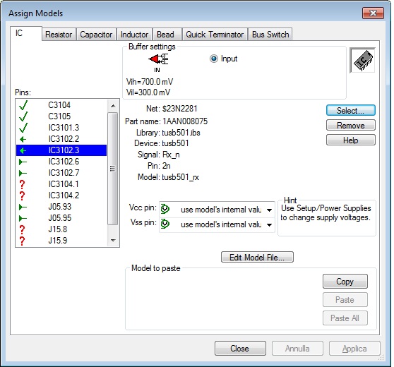
The picture show the model assigned to the TUSB501 redriver (IC3102)


This is the stimulus for the smd connector (SSTX output pair modeled as TUSB501 tx output pair):

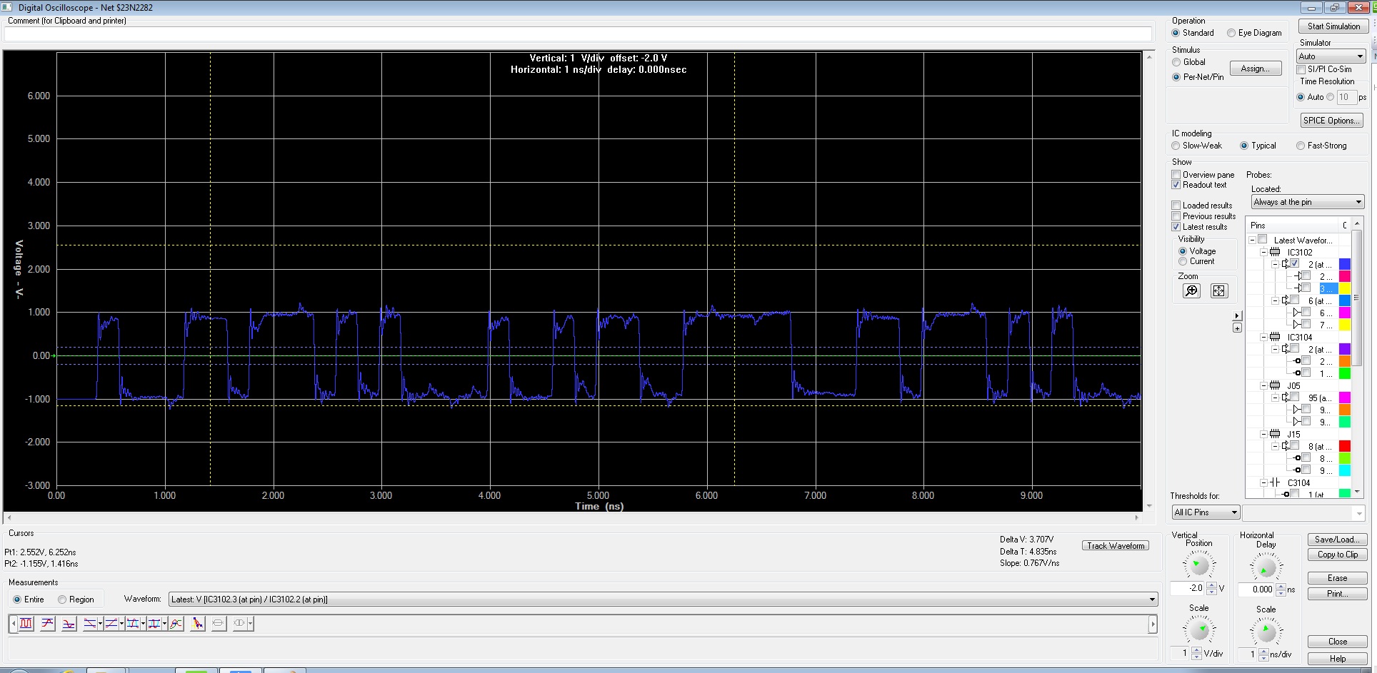
This is the IC3102 input signal at pin 2 and 3:

This is the differential signal
and this is the output signal at the output of the TUSB501 pin 6 and 7. I DON'T KNOW WHY

I have no signal at the output.
Please help me
Thanks


