This thread has been locked.

If you have a related question, please click the "Ask a related question" button in the top right corner. The newly created question will be automatically linked to this question.

SN65DP159: Register setting and input patterns for TPS1/2 and PRBS23 test

Part Number: SN65DP159


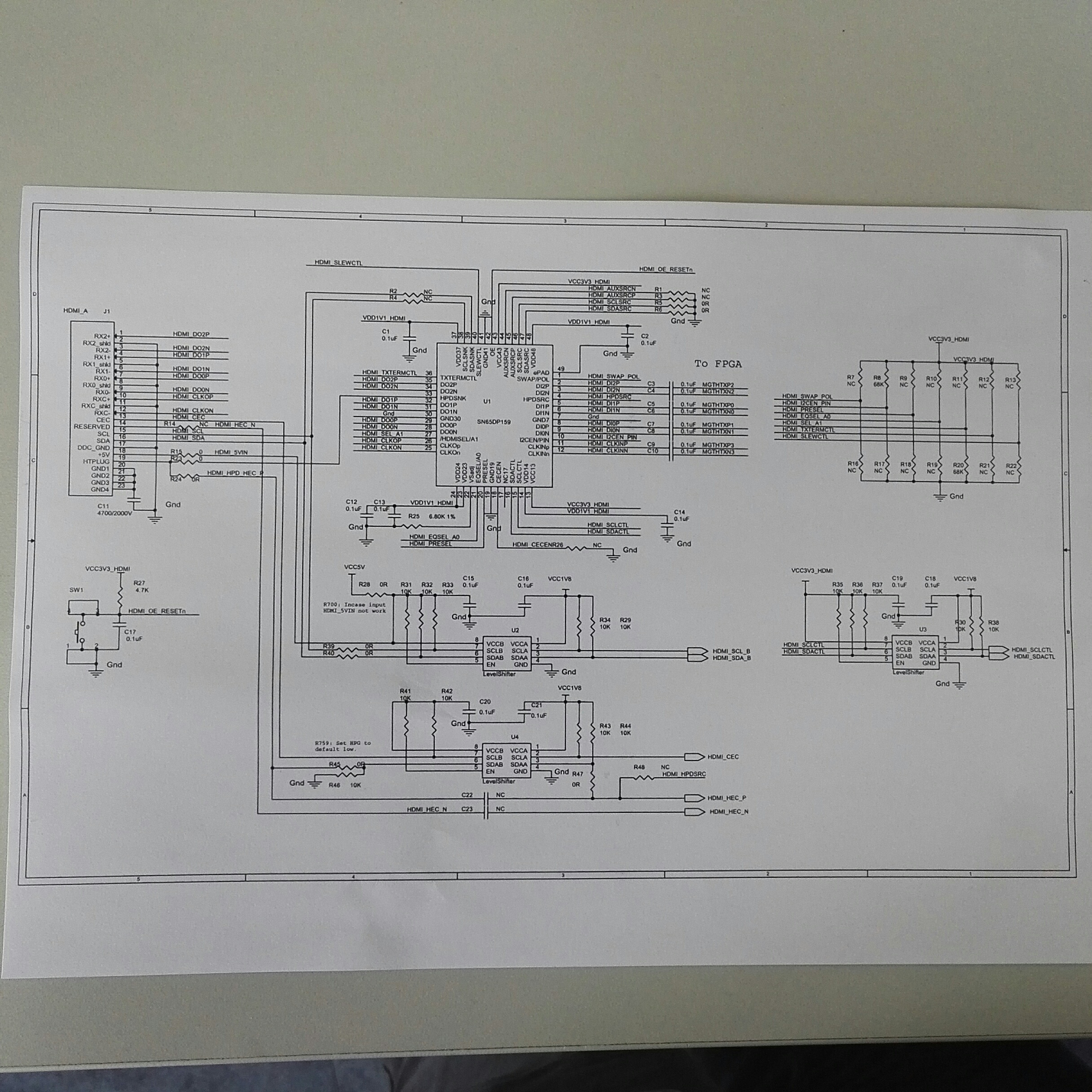
Hi TI, we are using SN65DP159 + FPGA to build a HDMI2.0 PHY(Max bit rate 5.94GHz, not display port), and the hardware connection is like this:

            LVDS(On PCB)                              LVDS(On PCB)                                TMDS(HDMI2.0 cable)
FPGA ----------------------> Caps(0.1uF)-------------------------> SN65DP159 ----------------------------------> TV set.

So far we can show color bars on the TV set for 4K30P and 4K60P, with SN65DP159 working in re-driver mode(for 4K60P, the color has some error).

Now we are trying SN65DP159 running in re-timer mode for 4K30P or 4K60P, but always fail. TV set recognizes the resolution formats and does show bars, but with definitely wrong colors. We have followed your guide in SLLA358 and some other on-line resources about this chip, but the problem is still there.

Below are my questions, the registers setting and the procedure of our work, please help to check, thanks a lot:

Q1: Are the registers setting and the feeding to SN65DP159 right for Step1-5 in main()?
Q2: What is the normal values read from 0x0f if we do PRBS23 verification as step5 in main()?
Q3: Is there any register to indicate the alignment status between ch0-ch2 on SN65DP159?
Q4: Or How can I align up ch0-2?
       FPGA can do phase shifting and bit slide for each channel, but what feed back can SN65DP159 give out to complete the adjustment?

//-- Register settings

void   main( )    {
//--1. Feed TPS1 to sn65dp159: ch0/ch1/ch2 with a 2.97G(1/2 BitRate) clock,
//                                                        ch ck with a clock of 148.5MHz.
tx_tps1();

//--2. sn65dp159 initialization
write_csr (0xFF, 0x00);

write_csr (0x09, 0x0a); // Power down and then power up sn65dp159.
delayms(100);
write_csr (0x09, 0x02);

initial_prog_dp159();

//--3. Do TPS1 test.
tp1_prog_dp159();

//--4. Feed TSP2 to sn65dp159: ch0/ch1/ch2 with repeated a pattern(K28.5-, D11.6, K28.5+, D11.6, D10.2, D10.2, D10.2, D10.2, D10.2, D10.2).
//                                                        ch ck with a clock of 148.5MHz.
tx_tps2();

tp2_prog_dp159();

//--5. Fed PRBS23 to sn65dp159: ch0/ch1/ch2 with PRBS23.
// ch ck with a clock of 148.5MHz.
tx_prbs23();

write_csr (0xFF, 0x00);
write_csr (0x10, 0x11);
write_csr (0x0e, 0x07); // Enable prbs23 check.
read_csr (0x0f); // To check the result: Should be 0x00? It reads unstable values on my test: 0xff, 0x0, 0x1e, ....

//--6. Fed normal video to sn65dp159: ch0/ch1/ch2 with tmds data,
//                                                                   ch ck with a clock of 148.5MHz.
//
tx_tmds();
}


void    initial_prog_dp159    (void)    {
printf ("\n Initializing DP159...");
write_csr (0xFF, 0x00); // Select Page 0
write_csr (0x09, 0x36); // Enable X-Mode
write_csr (0x0A, 0x7B); // Disable HPD_SNK pass-thru to HPD_SRC. Enable AUX
write_csr (0x0D, 0x80); // Clock on AUX is 1/20 datarate and enabled.

write_csr (0x0C, 0x6D); // Set TX Swing to MAX
write_csr (0x10, 0x00); // Turn off pattern verifier
write_csr (0x16, 0xF1); // Enable DP_TST_EN (disable char-alignment on all lanes)

write_csr (0xFF, 0x01); // Select Page 1

// CONFIGURE PLL BLOCK
write_csr (0x00, 0x02); // Enable Bandgap.
write_csr (0x04, 0x80); // PLL_FBDIV is 40
write_csr (0x05, 0x00); //
write_csr (0x08, 0x00); //
write_csr (0x0D, 0x02); // Selects Lane0 for clock.
write_csr (0x0E, 0x03); // CDR_CONFIG[4:0]. FIXED, LN0.
write_csr (0x01, 0x01); // CP_EN is PLL mode
write_csr (0x02, 0x3f); // CP_CURRENT
write_csr (0x0B, 0x33); // Test. May not use.
write_csr (0xA1, 0x02); // Oscillator enable.
write_csr (0xA4, 0x02); // Override enables.
write_csr (0x10, 0xF0); // ENTX Disable
write_csr (0x11, 0x30); // TX_RATE is Full Rate, TX_TERM = 75 to 150 , TX_INVPAIR = None
write_csr (0x14, 0x00); // HDMI_TWPST1 is 0dB de-emphasis
write_csr (0x12, 0x03); // SLEW_CTRL is Normal, SWING is 600mV.
write_csr (0x13, 0xFF); // FIR_UPD. Load TX settings
write_csr (0x13, 0x00); //

write_csr (0x30, 0xE0); // Disable Receivers
write_csr (0x32, 0x00); // PD_RXINT
write_csr (0x31, 0x00); // RX_RATE is Full
write_csr (0x4D, 0x08); // EQFTC = 1 and EQLEV = 2
write_csr (0x4C, 0x01); // Enable Fixed EQ (must not use adaptive when RX is disabled)
write_csr (0x34, 0x01); // Enable Offset Correction (gated by rx_ld) !!!!
write_csr (0x32, 0xF0); // Load Rx Settings
write_csr (0x32, 0x00); //
write_csr (0x33, 0xF0); // Load EQ settings

write_csr (0xFF, 0x00); // Select Page 0
write_csr (0x0A, 0x3B); // Enable HPD_SNK pass thru to HPD_SRC. Retimer.
write_csr (0xFF, 0x01); // Select Page 1
}


void    tp1_prog_dp159    ()    {

u8 rtxen, eqreg, tsten;
rtxen = 0x0F;
eqreg = 0x08;
tsten = 0xF1; // 1 : 0x11, 2 : 0x31, 4 : 0xF1

// Add all BW_handler processing here...
write_csr(0x00, 0x02); // Enable Bandgap, DISABLE PLL, clear A_LOCK_OVR (to reset it)
write_csr(0x01, 0x01); // CP_EN = PLL (reference) mode
write_csr(0x0B, 0x33); // Set PLL control
write_csr(0x02, 0x3f); // Set CP_CURRENT
write_csr(0x30, 0x0f); // Enable RX lanes
write_csr(0x00, 0x03); // Enable Bandgap, ENABLE PLL, clear A_LOCK_OVR
write_csr(0x4C, 0x01); // Enable fixed EQ (to reset adaptive EQ logic)
write_csr(0x4D, 0x08); // Set EQFTC and EQLEV (fixed EQ)

// Wait for PLL lock...
lock_cnt = 0;
lock_status = 0;
ReadBuffer[0] = 0;
while (ReadBuffer[0] == 0 && lock_cnt < lock_wait) {
read_csr (0x00);
ReadBuffer[0] = ReadBuffer[0] & 0x40; // 0x80;
lock_cnt++;
}

write_csr (0x10, 0x0f); // Enable TX lanes
write_csr (0x00, 0x23); // Enable PLL and Bandgap, set A_LOCK_OVR, and set expand LPRES
write_csr (0x02, 0x5f); // CP_CURRENT
write_csr (0x0B, 0x30); // Set PLL control
write_csr (0x01, 0x02); // CP_EN is PD mode
write_csr (0xFF, 0x00); // Select page 0
write_csr (0x16, 0xf1); // Set DP_TST_EN per #lanes, latch FIFO errors
write_csr (0x10, 0x00); // Disable PV (allows char-align and 8b10 decode to operate)
write_csr (0xFF, 0x01); // Select page 1
}


void tp2_prog_dp159 (XTmrCtr *InstancePtr, u8 link_lanecnt, u16 link_bw) {
write_csr (0x4C, 0x03); // Enable Adaptive EQ
write_csr (0xFF, 0x00); // Select page 0
write_csr (0x15, 0x18); // Clear BERT counters and TST_INTQ latches -- Self-clearing in DP159
err_cnt = read_csr (0x18); // Read core BERT counter [7:0]
err_cnt += ((read_csr(0x19) & 0xF) << 8); // Read core BERT counter [11:8]
write_csr (0xFF, 0x01); // Select page 1
}

  • Hello Shenghua

    Can you please, share the schematic of your application? I would like to take a look at it and figure out if something wrong with it. Can you also share the information regarding of video characteristics? like refresh rate, color bit depth, chroma sampling?

    Regards
    Francisco
  • Hi Fransisco,

    Thanks for your replay. We are trying a 3840x2160x60p video(4Kx2K60P) on the board, refresh rate: 60f/s, color depth: 8-bit,  YUV4:4:4, bit frate for ch0-ch2: 5.95GHz. 

    Actually, we have tried SN65DP159 working in re-driver and re-timer mode with color bars in different formats: 1080P60(ch0-ch2 bit rate: 1.485GHz),  4Kx2K30P(ch0-ch2 bit rate: 2.97GHz), and 4Kx2K60P(ch0-ch2 bit rate: 5.94GHz). Below are the results:

    Video format            SN65DP159  in re-driver mode            SN65DP159  in re-timer mode 

    -----------------------------------------------------------------------------------------------------------------------

    1080P60                    Ok                                                               failed

    4Kx2K30P                  Ok                                                               failed

    4Kx2K60P                  Color error in 2 bars                               failed

    "Ok" means  TV can show the color bars, and the color is right.

    "failed" means TV can show the bars, but color is totally wrong.

    It sounds we have not brought up the device working in re-timer mode.

    SN65DP159 is controlled by I2C in our case. and I will try to send you a picture of the schematic.

    Thanks,

    Shenghua

  • Hi Fransisco,

    My work PC has no connection with Internet, I just attached a photo of  the schematic here. I'm sorry it is not so clear.

     Thanks,

    Shenghua

  • Hi Shenghua

    Sorry but with the picture is a bit difficult to check the schematic. I attach a check list, please compare with your schematic and if you see something different, fix it and let me know your results.

    With a quick see, I couldn't find any capacitor at OE pin and it is necessary. If you have a pull up resistor on this pin, it doesn't need it because it has an internal pull up resistor.dp159Checklist.xlsx

    Regards

    Francisco

  • Hi Francisco,

    I checked the schematic with your list, and found 2 pins are NC: EQ_SEL/A0 and  SWAP/POL. For OE, we has a push-button and a 0.1uF cap on it.

    But the color bar is still wrong output from our board when EQ_SEL/A0 and  SWAP/POL are pulled down with 68K Ohm resistors to GND. 

    Is there any error in the procedure or register setting of SN65DP159 I listed in my 1st post?

    We didn't use the snoop function of the device on SCDC bus, so we set Reg[0x0B].[1]/[0] to 1s (on page 0)for working with HDMI2.0 4Kx2K60P video. Is it ok?

    In PRBS23 check on the device, what is the value read from Reg[0x0F](Page0) if all thing is ok? We tried such test, and Reg[0x0f] read 0x1e, 0x00, ..., always changing.

    Thanks,

    Shenghua

  • Hi Shenghua

    According to the description in your first comment, I would like to confirm somethings. What kind of source are you using? Do you have LVDS signals? if so, unfortunately, the DP159 is not the correct device, this device works with AC-coupled TMDS signals and Display Port Dual mode. We have other devices that can handle this one.

    Regards
    Francisco
  • Hi Francisco,

    The source we fed to SN65DP159 is a video(3840x2160, 60f/s) from an HDMI2.0 TX,  TMDS encoded, serialized, and transferred in LVDS mode.  

    Thanks,

    Shenghua

  • Hello Shenghua

    Sorry for my delay, I was out of the office. The problem that I can see is that you handle LVDS mode in the input and these signals are different, can you send these signals through TMDS. This device is able to work with AC-coupled TMDS or display port dual mode. If you can test with this kind of sources I think you should have good results.
    On the other hand, I also took a look at you schematic again and I saw that your I2C pull-ups resistors are wrong. We recommend using 2k pull up resistors. Can you upload the schematic in pdf format? I would like to check it with detail.

    Regards
    Francisco
  • Hi Francisco,

    Thanks for your effort and help. My problem is mainly in the re-timer working mode of SN65DP159.

    As you noted, I changed the pullups on I2C bus to 2K, but the issue is till there. I also checked the input to SN65DP159, Vswing(Vpp of the differential inputs) is in the range. And the display on TV of a 4kx2k3p color bar is ok in re-driver mode, so maybe the failure in re-timer mode is due to input timing, register setting or something else, but not the input mode. 

    In re-timer mode, does the chip re-align the captured signals from the 3 data channels? If yes, when does it  align the data? What special data pattern should be fed to it? 

    I also want to adjust the output timing(kind of alignment) on FPGA side for the 3 data channels by S/W, but how could the S/W know a special delay is ok for a channel? Does SN65DP159 have such feedback clue in registers?

    (Although I think it is necessary, but I am sorry I have no means to upload the pdf file of our schematic. Company's policy blocks the outflow.)

    Thanks,

    Shenghua

  • Hello Shenghua,

    From the original E2E post, it appears that you are using the sample code for xmode of the DP159.  Xmode should only be used if the DP159 is being used as a DP to DP retimer.  That does not appear to be your use case.   Try running the DP159 without that code, just using the default pin configurations, you should be able to see the retimer mode work properly.

    Regards,

    JMMN

  • Hello Shenghua,

    As JMMN says, please try to test just using the default pin configurations, and let us know your results. On the other hand, if you want, you can send me the schematic by email, let me know if that is possible and I can send you an email.

    Regards
    Francisco
  • Hi Francisco and JMMN,

    I tried the method JMMN mentioned, it really works, and I just set 2 registers(Reg[0x0b]=0x9b, then Reg[0x0a] = 0x3f) after reset, the TV can show the color bar now. Thank you very much.

    BRs,

    Shenghua