This thread has been locked.

If you have a related question, please click the "Ask a related question" button in the top right corner. The newly created question will be automatically linked to this question.

TLK1221 hold time measure on RX of TBI

Other Parts Discussed in Thread: TLK1221

Hi All:

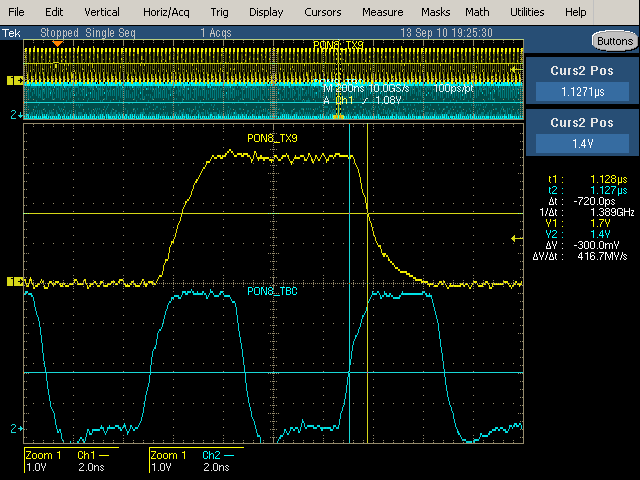
 Because TLK1221 datasheet didn't show out TX data timing, customer followed figure 9 to measure hold time.
Our spec. min. hold time is 0.8ns, but customer got 0.72ns.
Could you tell me whether test condition something wrong or not.
Ex: rise time falling time measure voltage is 1.7V or others.

Please help me to confirm the hold time measured point or offer the TX timing
figure, thanks a lot.

  • Thomas,

    I believe you are referencing the wrong parameter in the datasheet for what you are testing.  The parameters for the TLK1221 LVTTL Output Setup and Hold are tsu(d1) and th(d1) with a minimum hold time of 2nS at 125Mhz or 4nS at 61.44nS.  Please note that the single ended "output" signals are RD0-RD9 which would be the de-serialized data from the High Speed Receiver.  The appropriate timing diagram to use as a reference for this parameter is Figure 3.

    The 0.8nS parameter you were referencing is the minimum hold time needed on the single ended inputs TD0-TD9 which would be the parallel data provided to the TLK1221 to be serialized and transmitted on its high speed output. 

    Regards,

    Jon

  • Thanks forJon reply.

    Previous waveform was measured TD9 and clk by customer to get hold time 720ps, but that could not meet 0.8ns min.spec.

    Could you give me a TD0-9 wave form as like figure 9. that show out Data and clk measure dvoltage points?

    For example: CLK:1.4V , TD0-9 :1.7V or 2V start to calculate hold time

  • Thomas,

    Let me make sure I understand your questions.  Is the customer trying to measure the Parallel Input Hold time, or the Parallel Output Hold time?  If they are trying to measure the parallel input hold time, does the waveform you provided show the signals the customer is placing on the TLK1221 TD9 pins?

    If the customer is trying to measure the parallel output hold time, the waveform could not show the signals from the TD9 pin because the TD9 pin is an input pin.

    Also, Figure 9 is a figure of the Rise and Fall time and is completely unrelated to Setup and Hold measurements.

    Please clarify if they are trying to measure the input or output hold time.

    Thanks,

    Jon

  • Hi Jon:

    Customer wanted to measure parallel input signal (TD9) hold time.

    Because hold time just show out in RD as like figure 3 in datasheet, I post tiltle is RX measured.

    I am sorry that maybe confuseyou.

  • Hi Thomas,

    The input setup timing setup spec of 1.6nS indicates that TD(0-9) data signals should be stable for at least 1.6nS prior to the REFCLK edge.  This is a minimum number that must be met per the datasheet to ensure the data is sampled properly.  Likewise, the minimum hold timing spec of 0.8nS is the amount of time the TD(0-9) data must remain stable following the REFCLK edge to ensure the data is properly sampled.  It would be preferred that the data is stable for greater than 0.8nS and both the setup and hold time each equal 0.5UI.  Their measured hold number of 0.72nS exceeds our spec of 0.8nS and would indicate that for their test setup we have 0.08nS of margin before we would fail this parameter.