This thread has been locked.

If you have a related question, please click the "Ask a related question" button in the top right corner. The newly created question will be automatically linked to this question.

TCA9509: The step at the logic high of rising edge

Part Number: TCA9509
Other Parts Discussed in Thread: TCA9548A

Hi Team,

  My customer meet a problem on TCA9509,there is an step on every rising edge of SCLA and SDAA when host send data to slave(TCA9509 is slave),the step is locate at the logic high as below shown.

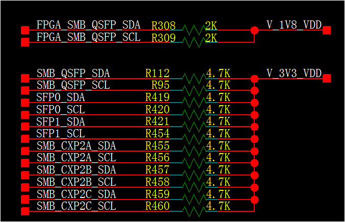
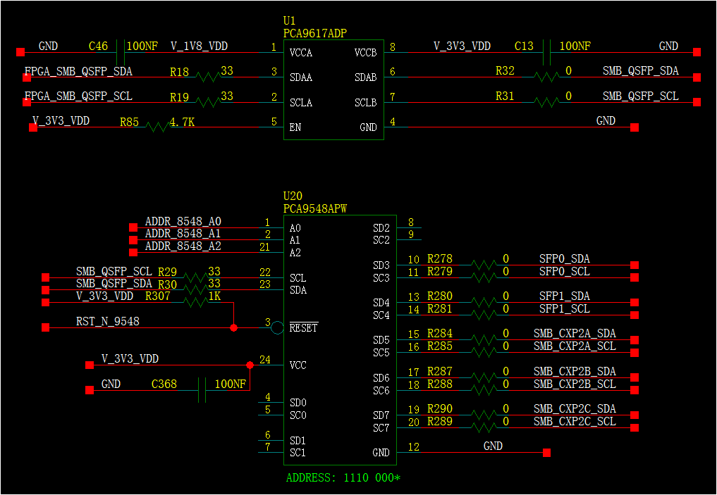
The connection is FPGA<--->I2C BUSA of TCA9509<-->I2C BUSB of TCA9509<-->PCA9548<-->optical module

When FPGA send data to TCA9509 every rising edge of SCLA and SDAA have such step.

When TCA9509 send data to FPGA,there is step at SDAA,but every rising edge of SCLA has such step.

Could you help check the reason of step and is there any risk for I2C operation?

Green curve =SCLA

Purple curve =SCLB


Best Regards,

Nick Dai

  • Hello Nick,

    I was wondering if we could get a schematic of your customers circuitry to make sure system is implemented properly.  If it is proprietary then you can email it to me. 

    This seems like a weird problem. 

    • Is their FPGA separate from the TCA9509 and TCA9548A?  Are there a long lead and is there potentially a ground offset?  
    • Does the A side have a external pull up resistor or does the FPGA has an internal pull up resistor?    This part is designed to not have a pull up resistor on the A side because it has a constant current source pulling up the bus. \
    • Is there a potential difference between the VCC of the FPGA and the VCCA of TCA9509?  If so, is it about 150mV?  Where is your scope probe grounded?  I am thinking the step is due to the constant current source turning OFF and the step is due to supply voltage difference.  Schematic with details of what was measured and wear will help with debug. 

    In short, it shouldn't affect the High logic levels used by I2C devices, but we should know where the step is coming from.  I am more worried about any potential differences affecting the low, rather than the high.  

    Can you confirm that Vcca=1.8V and Vccb=3.0V?  Again, schematic would help use see potential problems.   

    -Francis Houde

  • Hi Francis,

       Thanks for your support.

       There is no connection between FPGA and TCA9548,and the customer used same VCC for FPGA I2C and TCA9509 BUSA.

        They tried to pull EN pin of TCA9509 to low,and then there is no step on busA of TCA9509.So it seems the problem is related with the operation of TCA9509 busB.

       The schematic of customer design are shown in below. 

       The part number PCA9617 should be TCA9509.

       The customer replaced all 33ohm series resistors by  0ohm ,but the step was still there. 


    Best Regards,

    Nick Dai

  • Hello Nick,
    Can you have them remove R308 and R309? They should not have pull up resistors on the A side when using the TCA9509. See if this takes care of the problem.
    -Francis Houde
  • Hi Francis,

      The customer already tried to remove the pull up resistors on A side of TCA9509,but the step was still there.

      Without R308 and R309,the customer also removed the R29 and R39 to disconnect TCA9548 with B side of TCA9509,but the step was still there also.

      There was not such step when pull EN pin of TCA9509 to low.

      Is there any other clue for this issue?

    Best Regards,

    Nick Dai

  • Hello Nick,
    I noticed that the rise times on the leading edge is very fast. Are they sure they have the pins setup as an open drain? It almost looks like it is setup as push-pull. Please have them verify that it is setup as open drain.
    -Francis Houde
  • Hi Francis,

    Thanks for your feedback.
    Do you mean the I2C port(GPIO) setting of FPGA seems like push-pull rather than open drain?

    Best Regards,
    Nick Dai
  • Yes, that is correct.
  • Hi Francis,

    The customer is checking the port configuration of FPGA I2C.
    Could you help check is there any risk if the customer connect 100ohm resistor(R23,R24,R25 and R26) at the output TCA9548? When the channel of TCA9548 was selected,the B side of TCA9509 will connect with this 100ohm resistor by TCA9548.
    They used 100ohm resistor to protect the device due to the optical module will be hot pug in sometimes.

    Best Regards,
    Nick Dai
  • Hello Nick,

    It is ok to add a series resistor as long as you not that it does change the VOL from the slave device of the other side of the connector.  You get a resistor divider and as long as the pull up resistor value is large enough to make sure the master sees the correct voltage to meet VIL then you are fine.  You can get into trouble with the series resistor when there are large capacitive loads and in order to meet I2C rise time specifications you need a strong pull up (lower resistance value) which shifts up your VOL from the slave. 

    -Francis Houde