Part Number: TUSB211
Hello.
In our application (a camera with USB2.0 interface) we have serious problems with emissions on 480MHz and 960MHz.
The camera has a 3 meter cable connection to the USB interface.
The USB connector is mounted on a PCB where we added a current protection circuit and a TUSB211 signal conditioner.
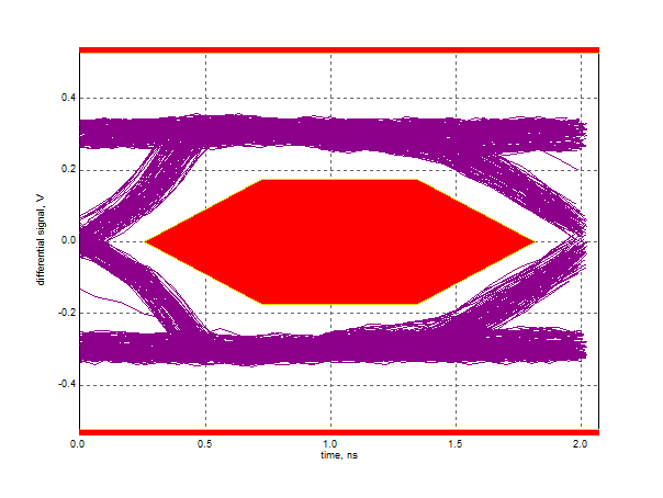
The signal conditioner is required to have a good eye pattern, especially at the moment we will be using an extension cable (1 or 2 meter).
The emission levels are approximately 10 dB above the limits. The equalisation factor is set to level 1.
The PCB layout is according the datasheet proposal.
The signal conditioner is mounted very closely to the USB connector. We believe that the emission is coming from injecting current into the datapair.
We tried several PCB layout concepts, shielding concepts but nothing seems to work properly.
We tried to add common mode coil, this improves about 10dB (we need to have some more).
Any suggestions would be highly appreciated ....