This thread has been locked.

If you have a related question, please click the "Ask a related question" button in the top right corner. The newly created question will be automatically linked to this question.

DS90UB928QEVM: No LVDS output from EVM

Part Number: DS90UB928QEVM
Other Parts Discussed in Thread: DS90UB927QEVM, ALP

Hi,

Customer of mine intend to use DS90UB927QEVM and DS90UB928QEVM to output the LVDS signal from Head Unit to LCD as shown in the diagram below.

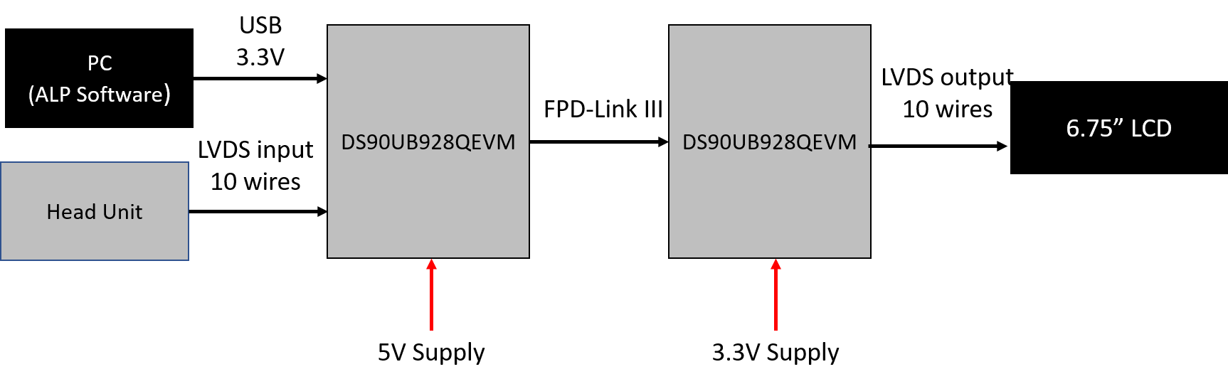
The actual connection is below

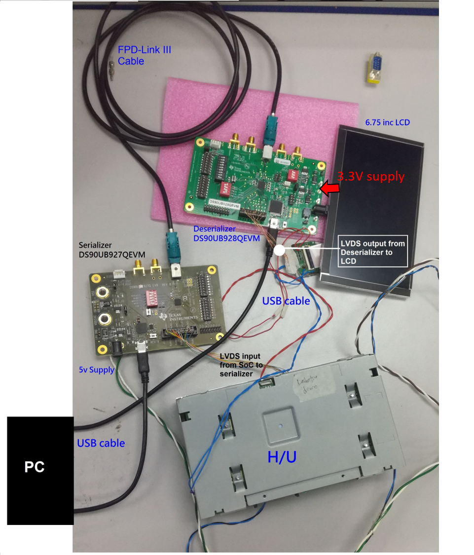
We've also confirmed that the DS90UB927QEVM was connected to ALP. However, after having all the setup and supply connected, they still couldn't see any output on LCD.

Below are my questions:

- Do we need any external circuitry such as ext CLK, pull up resistor for 927/928?
- Do we need to set any register in ALP in order to output the LVDS signal?

Look forward for your favourable advise 

  • Hello,
    LVDS signals should pass through if devices are configured to proper mode and enabled. The OLDI CLK is provided to the 927 EVM by the head unit and should be visible at the output of the 928 OLDI CLK. The wiring on the OLDI does look somewhat suspect for good connection. Please verify link functionality with lock and pass for the FPD-Link and reference the EVM user guide.
  • Hello Liam,

    Thanks for your prompt respose.
    I don't quite understand the OLDI CLK you mentioned.
    (1) Could you indicate/advise me the location of OLDI CLK?
    (2) one more question, if the FPD-LINK is established between 927EVM and 928EVM , I should expect the LOCK LED turn ON right?

    Thanks

  • Hello,

    For the questions:
    1) It means the input video includes the clock, which are RxCLKIN +- pins on 927;
    2) Yes, if the link is established, the LOCK LED should be turned on.

    Suggest you to disconnect the LVDS input and the LCD output, and try to get the link between 927 and 928 evm first. 927 can generate patterns for test.

    Regards,
    Cera
  • Hello Cera,

    Thanks for your advise. I will check the input signal as well as RxCLKIN +- pins
    I'm rather new to 927/8, could you teach me how to generate the patterns?

    Correct me if I'm wrong, without the LVDS input and LCD output, the connection should be like this:?
    ALP (PC) <-> 927 <--> 928
  • Hi,

    Yes, the connection is right.

    You may generate the pattern on ALP, see the picture below.