This thread has been locked.

If you have a related question, please click the "Ask a related question" button in the top right corner. The newly created question will be automatically linked to this question.

TCA9535: TCA9535 Basic Operation and the corresponding I2C needed to toggle an LED of Interest

Part Number: TCA9535


Hello,

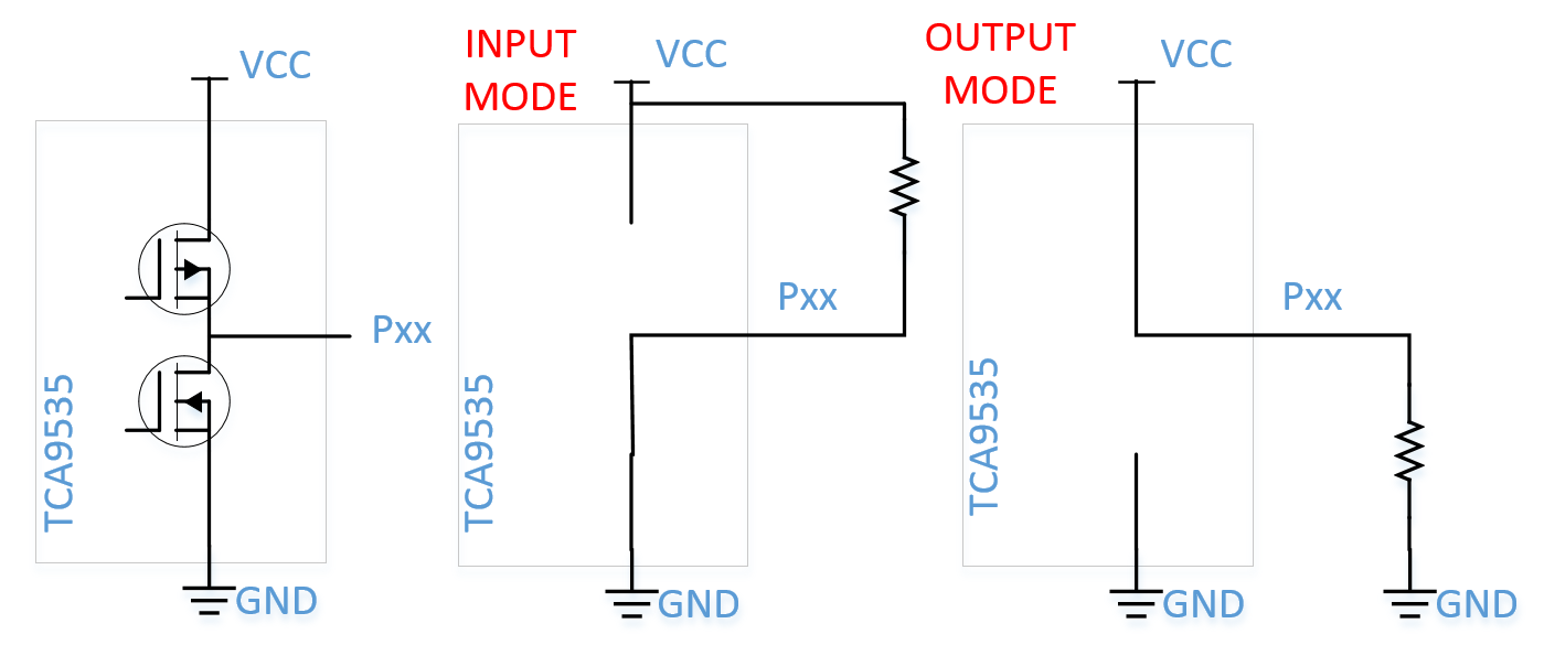
Im looking into using the TCA9535 in hall sensing EVM where I am a little short on microcontroller pins and thus am interested in using a I/O expander like the TCA9535 to light up all of my LED indicators.  Currently I am trying to get a better understanding of the devices operation.  As of now, I am under the impression that an given I/O pin on the TCA9535 at basic high level view has a structure similar to the left figure below.  Subsequently, the device can be operated like what I have in the two figures on the right.  Is this correct?

So now if I had a setup like the following figure below, would turning on an LED be as simple as configuring the pin from input to output.  Or do I need to first configure the pin to be an output and then toggle the polarity bit to turn on and off?

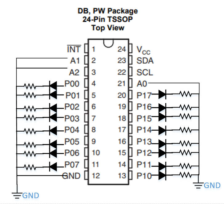
If the first option is correct, if I want to light up a LED on P00, would my I2C pattern be like the one below?  Or if it is option 2, would the I2C pattern be like the other one below?

  • Hey Patty,

    The input mode for the TCA family does not have an internal pull up resistor, instead you should think of it as a floating high z. If you plan on using the device as an input, it would best to tie a pull up resistor to these.

    The output mode is a push pull architecture. If the output is set as a logical 1 or high, then the PFET will switch on to connect the output to Vcc. However if you have the output set to a logical '0' or low, then the NFET will turn on and pull the output low to GND.

    "So now if I had a setup like the following figure below, would turning on an LED be as simple as configuring the pin from input to output.  Or do I need to first configure the pin to be an output and then toggle the polarity bit to turn on and off?"

    -You will want to set the configuration register to be outputs; they start in default as  inputs. I would recommend you set the output registers to '0' first so all the outputs are 'low' and when you set the configuration register, they will not be all turned on at once but start as off.

    This would look like:

    First transaction

    start----0x20h(slave address) 0(write)----ACK----- 0x02h(Command byte of Output port 0) -----ACK----- 0x00h(port0 outputs low)----ACK--0x00h(set port1 outputs to low)---Stop/Restart

    //this will set the outputs to be low when they are configured as outputs but you can skip this step if you want them all to be on when you set the ports to outputs.

    Second transaction

    start----0x20h(slave address) 0(write)---ACK---- 0x06h(Command byte of configuration port 0)---ACK---- 0x00h(set port0 as outputs)----ACK--0x00h(set port1 outputs to low)---Stop

    //this will turn the ports to outputs

    Note that we are able to write to Configuration port1 and Output Port1 within the same transaction due to the auto increment function of the device.

    Lastly, please take note of page 5 specifying the maximum current source capability:

    Thanks,

    -Bobby :)