


Part Number: TPS65982
Hi Team,
We are building a manufacturing test/debug board using the TPS65982. We have a TPS65982 controlling the USB-C port on our main project board and we are intending to use one on the debug board. I would like to have the debug board present itself as a debug accessory so that I can put the TPS65982 on the main board in to Debug Accessory Mode.
Do you have any more information other than the small section (7.2) in the FW User's Guide about how to use the Debug Accessory Mode? I’m assuming that I need a special/modified cable, probably directly attached to the debug board which does not break the connection on one of the CC pins so that the main board sees Rd on both CC wires.
Assuming that I can get the TPS65982 on the main board into Debug Accessory Mode, is it possible to do a normal USB-C PD negotiation while in Debug Accessory Mode? The TPS65982 in Debug accessory mode on the main board will configure its internal mux’s to expose some internal signals, is it possible to configure the mux’s in the TPS65982 on the Debug board in a similar way to break out those signals?
There seems to be very little documentation about Debug Accessory Mode and I was only able to find one relevant E2E post , so I’m hoping you can help me figure out how to get what we want out of it.
I've include a simple block diagram to show what we intend to do with only a small modification. Instead of discrete resistors we would like to use the TPS65982 internal resistors for the CC pins on the debug board. 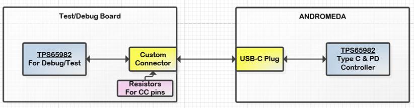
One last question... we plan to utilize the full 100W of power that PD offers, but have yet to find any 100W adapters/power bricks on the market to test our product with. Are you aware of any or is the only option to use a Power Supply & E-Load to test the 100W?
Please let me know what additional information you need and/or what questions you have.
Regards,
Hayden

