This thread has been locked.

If you have a related question, please click the "Ask a related question" button in the top right corner. The newly created question will be automatically linked to this question.

PCA9536: PCA9536 - register #2 (Polarity Inversion)

Part Number: PCA9536

Hi E2E,

I got feedback from customer that rigister #2 data of PCA9536 is 0x01 read at power up stage without any writing. it didn't match the describtion in datasheet as default setting as 0x00. any reason will cause register #2 change the default setting?

BR,

Jason

  • Hi Jason,

    Are all other register read/wrIte operations working well? If not, there may just be some I2C communications issues. If the register really does have the wrong value at startup, though, it may be due to the power on reset not activating properly. Can you please confirm the power ramp guidelines described in Section 9.1 of the datasheet are being followed?

    Regards,
    Max
  • Hi, Max

    It read PCA9536 status at system ready.
    PCA9536 only read register 0x0, 0x2 and 0x3. Register 0x0 = 0xff is our PASS criteria condition (read register 0x02 = 0x0 at once).
    But register 0x2 value is random, it can impact register 0x0.
    (ex. PCA9536 read 1st 0x41 reg0 = 0xfe
    PCA9536 read 2nd 0x41 reg0 = 0xfe
    PCA9536 reg0x02=0x01, reg0x03=0xff)
    For registe 0x3, its value sometimes random
    What function is for register 0x3?

    Thank you very much
  • Hey Ching Su,

    "What function is for register 0x3?"

    -Register 0x03 is the configuration register of the device. It determines whether the device's ports are outputs or inputs.

    Were you able to confirm your device was powering up correctly? We have a power on reset errata on the datasheet on page 20 section 9.1. Please confirm there are no issues with this. If you are able to get a scope shot of the device's Vcc during power up, it may provide us with clues. Also are you able to show us a picture of the schematic?

    Thanks,

    -Bobby

  • Hi, Bobby

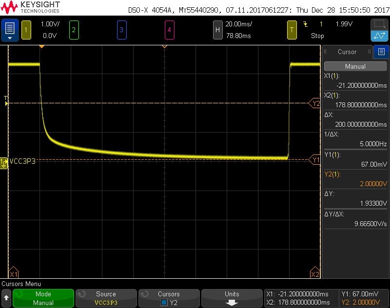
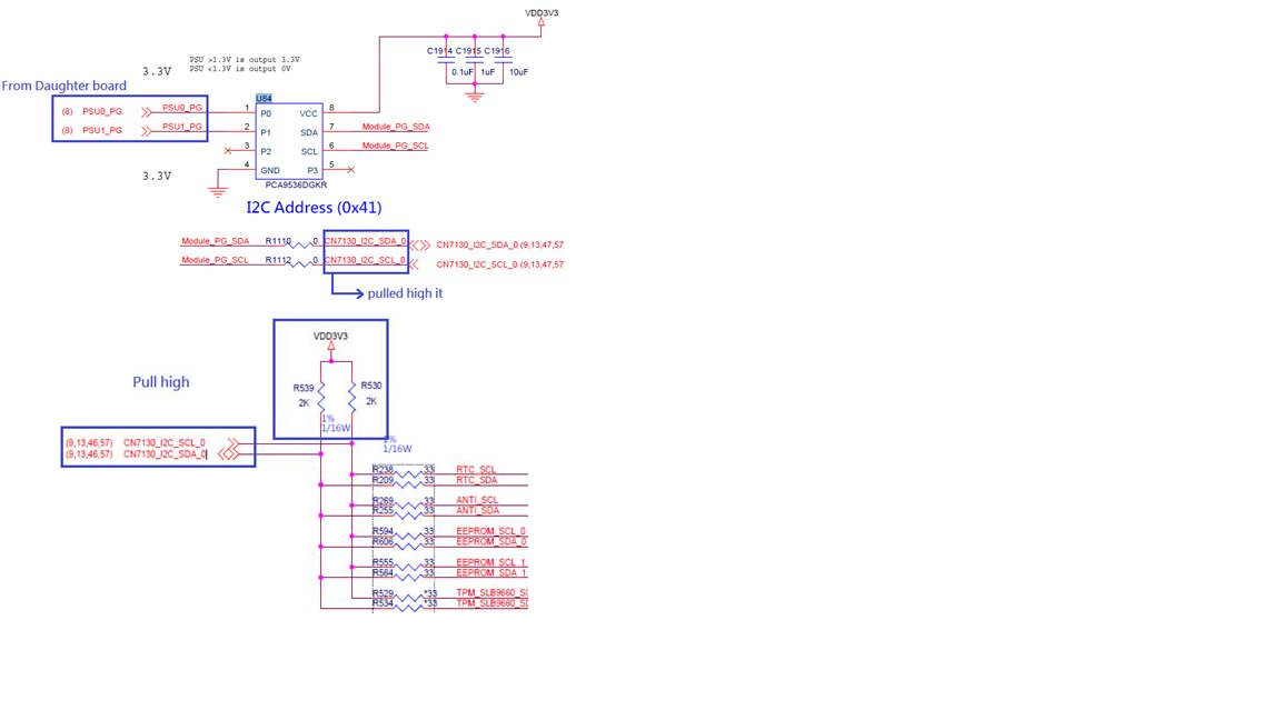
    Please kindly see attached picture for VCC power on reset and PCA9536 schemtic

    PSU0_PG and PSU1_PG is from daughter board

    Daughter board schemtic↓

    Main board schemtic↓

    Scope ↓

    Thank you very much

  • Posted thier schematic.

  • Thank you for the additional information.

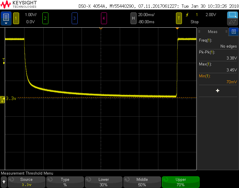
    Looking at the o-scope shot, your Vcc waveform looks good when it is ramping up but during the ramp down it begins to slow down. The ramp down itself looks like a capacitor discharging; a colleague of mine ran into this issue of the internal registers sometimes changing from default state during POR before; due to this ramp down slewing. In his case, I believe he was able to resolve this problem by placing a pull down resistor on Vcc to allow for a faster slew rate when powering down.

    Actions:

    1) Can you remove the 1uF and 10uF capacitors next to the device from Vcc? It is affecting the ramp down slew rate of our device.

    2) Please add a pull down resistor on Vcc to GND (next to our device) and check to ensure Vcc ramps down faster. I would probably try a value like 10k and work my way down (lower) and checking the Vcc pin on the o-scope until it looks similar to the rise time. [Lower will have faster fall times at the expense of power consumption]

    -After adding the pull down resistor, please check the default states of the registers again

    On my end, I will discuss this problem with my colleague when he gets back from vacation, on Tuesday, to double check with him on how he resolved the past issue. (Very similar to your case)

    Thanks again,

    -Bobby

  • Hey Jason,

    I just wanted to double check, was this customer problem resolved? If so, was it done with using the pull down resistor?

    -Bobby
  • Bobby,

    customer is busy on other task and they will update the result next week.

    BR,

    Jason

  • Hi, Bobby

    Sorry, reply for late

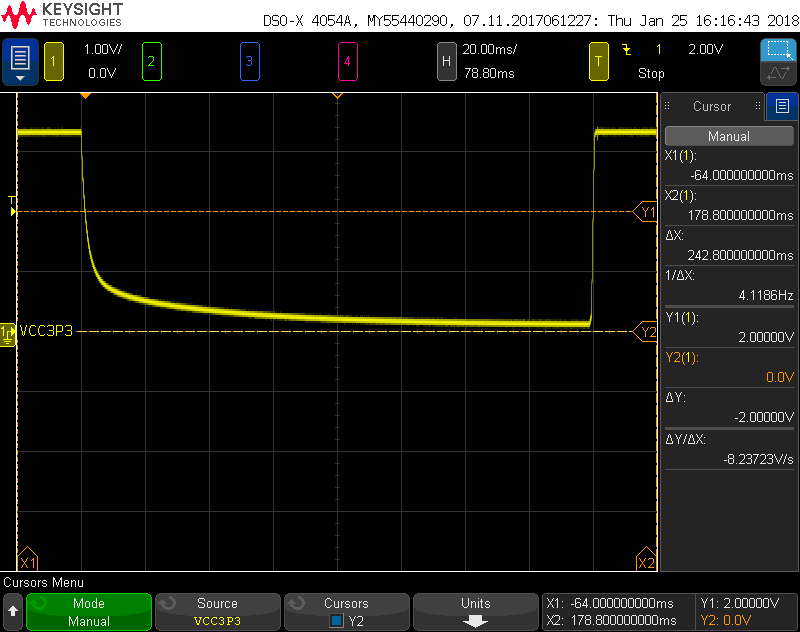
    I measure 2 kind of solutions, and capture the scope picture for you

    Do you have any suggest or command to measure for us?

    Please kindly see attached file

    Thank you vert much

    1. Remove C1915(1uF), and C1916(10uF)

    2. Add 10Kohm in C1915

  • Hey Ching Su,

    Thanks for the scope shots. I spoke with another engineer on the team who ran into this issue before and stated it was fixed by pulling Vcc all the way to GND (not floating a little bit above). It looks like we are still seeing the device decay very slowly without fully hitting ground. Do you have any other large capacitances on this bus? Are you able to provide an estimate of how much capacitance is on the bus as well?

    We can try sizing down the pull down resistor to 5K or 1k and try to get the pull down to GND.

    Thanks,
    -Bobby
  • Hi, Bobby

    It is many capcacitance in PCA9536_VCC, PCA9536_VCC is Main board VCC3P3 DC power.
    Do it try to test pull down 1kohm or 5kohm in PCA9536 VCC side?

    Thank you very much

  • Hey Ching Su,

    "Do it try to test pull down 1kohm or 5kohm in PCA9536 VCC side?"
    -Yes, please try both resistances and also can you get the time difference for me when the signal goes from 70% to 30%? I can try to back calculate the estimated capacitance from this.

    Thanks,
    -Bobby
  • Hi, Bobby

    Sorry, replay for late

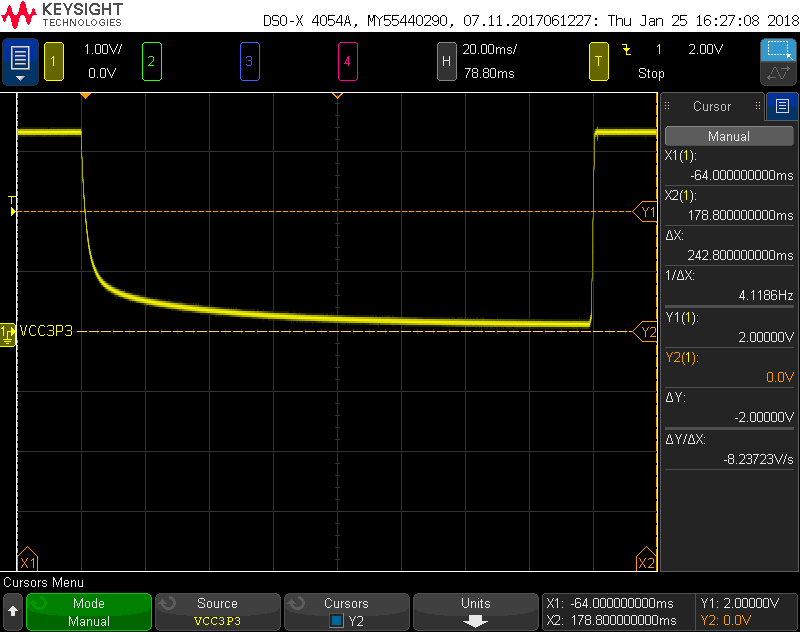
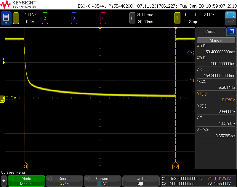
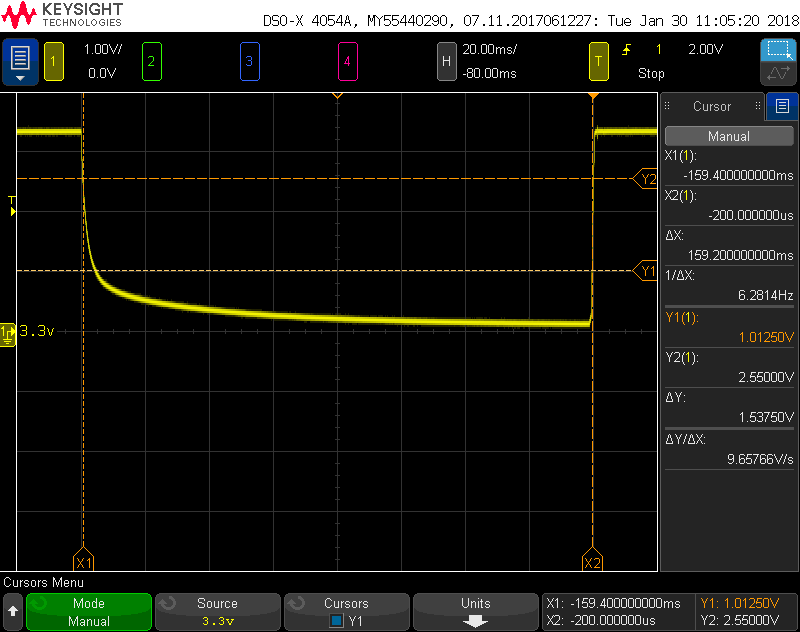
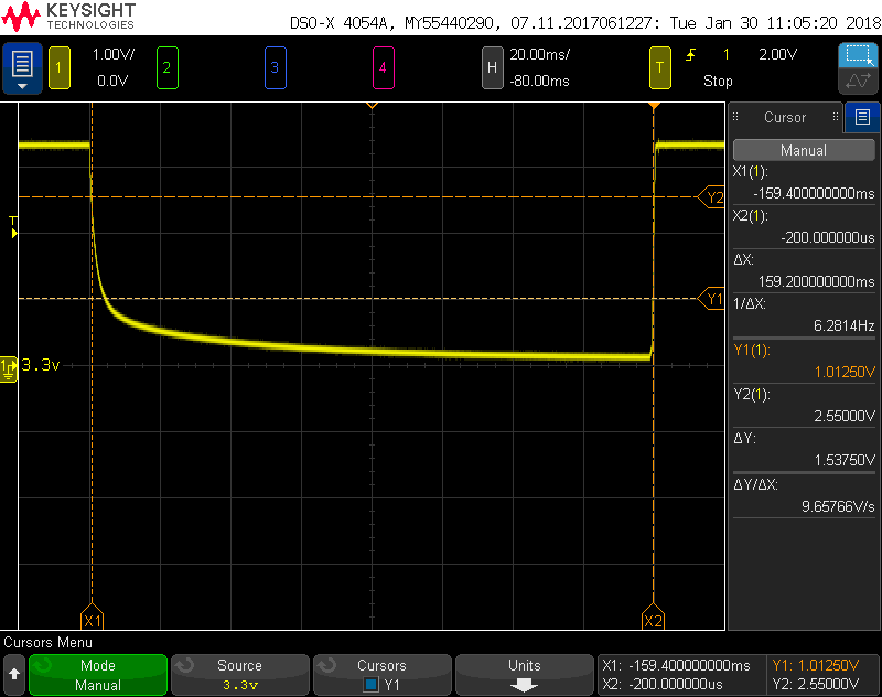
    Please kindly refer the scope picture

    Thank you very much

    1. C1914 used 0.1uF, C1915 used 1kohm, C1916 un-used

    2. C1914 un-used, C1915 used 1kohm, C1916 un-used

    3. C1914 used 0.1uF, C1915 used 5kohm, C1916 un-used

    4. C1914 un-used, C1915 used 5kohm, C1916 un-used

  • Hey Ching Su,

    In your pictures you have the X1 and X2 in the wrong spots, I need them to be on top of the 70~% point of the falling edge and the 30% point of the falling edge to see the deltaX values. It's difficult to see what these times are currently for me to estimate the capacitance.

    From looking at the wave forms, it looks like the Vcc line does not actually hit 0V but hovers at 70mV (this could just be the o-scope though)..... Have you tried testing our device and seeing if the register values match the expected default settings using these pull down resistors?(does problem still occur?). If we are still seeing issues then we may need to find a way to pull Vcc all the way to GND.

    Thanks,
    -Bobby