This thread has been locked.

If you have a related question, please click the "Ask a related question" button in the top right corner. The newly created question will be automatically linked to this question.

TUSB4041I-Q1: TUSB4041I-Q1 high current drawn by VDD 1.1V rail

Part Number: TUSB4041I-Q1

Hi,  

I am using TUSB4041I-Q1 USB HUB on my custom hardware. I have used two regulators, 3.3V for VDD33 & 1.1V for VDD.

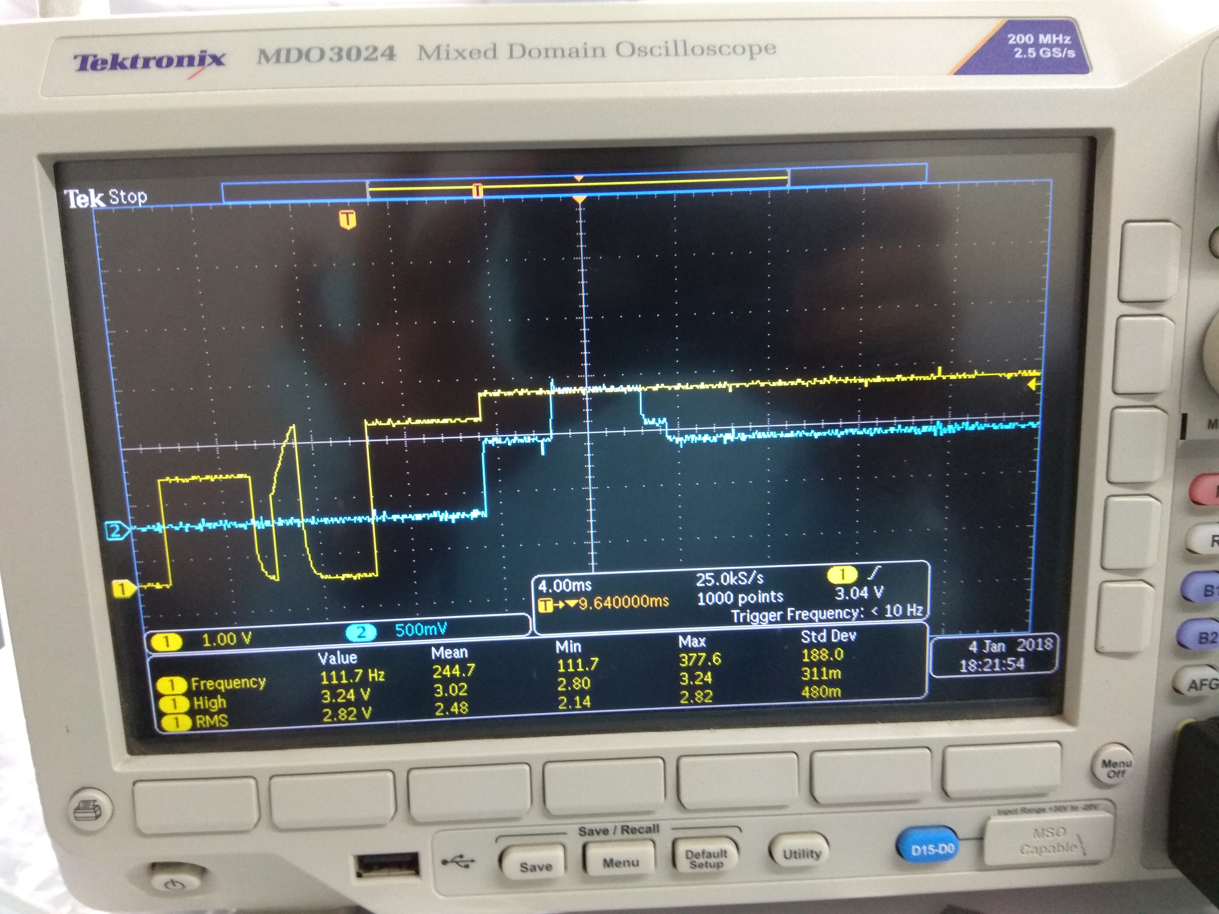
While applying power to the board, observed that 1.1V rail voltage drops down to 0.65V. See the waveform attached below. Yellow Signal - GRSTz, Blue Signal - VDD 1.1V rail.

Any idea about the cause.??

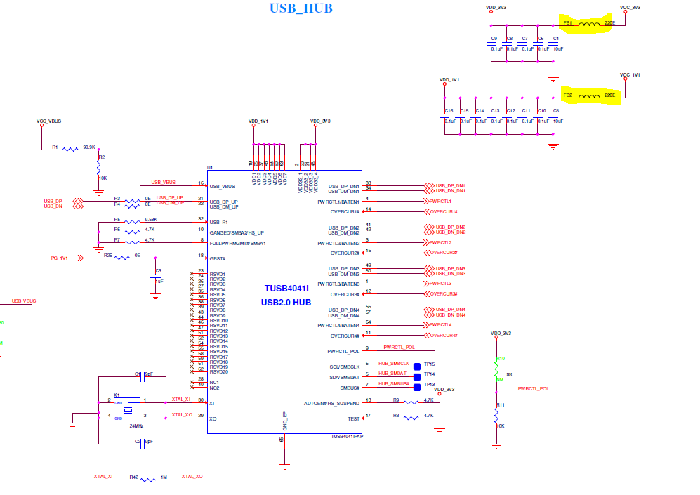
See USB HUB Schematic for the review reference from below link.

Appreciate the earliest response.

Thanks,

Ritesh

  • Hello Ritesh,

    Can you plese provide the part of the schematic showing the 1.1V regulator? How much power is your power supply capable to provide?
    TUSB4041 can draw over 250mA from the 1.1V power supply while the device isn't configure. You need to make sure the power supply can handle that and any other components that may be connected to that supply.

    Additionally, GRST signal behavior looks wrong to me. Make sure the signal is steadely asserted (low) during the whole power-up and until at east 3ms after both power supplies are stable.

    Regards,
    Jorge
  • Hi Jorge

    Thanks for the quick response.

    Our 1.1V LDO supports 150mA and it should be higher than max current in TUSB4041I-Q1.

    We are not controlling GRSTz pin. We are only powpowering USB hub.

    Which configurations are required? Can we set using hardware setting?

    Thanks.

  • Hello Ritesh,

    If your 1.1V LDO can only provide 150mA, that should be the problem. As mentioned above, TUSB4041 will draw up to 250mA by itself before being configured.

    Device configuration will be automatically loaded some time after GRST is de-asserted.
    If no EEPROM is present nor SMBus mode is enabled, then default configuration will be loaded from internal ROM.
    If SMBus mode is enabled (SMBUSz terminal is low during reset) configuration should be provided using an SMBUS master, and the device will remain in an unconfigured state until the CFG_ACTIVE bit is cleared.
    In your case, according to your schematic, configuration will be loaded from the external EEPROM.

    If no active reset is being implemented (Not controlling GRSTz), the recommended power-up sequence is to have VDD11 stable for at least 10us before enabling VDD33. Besides you will need to add a capacitor to the GRSTz terminal as shown on figure 32 on the datasheet.

    If above condition cannot be achieved, it is recommended to have an active reset to assert GRSTz low for at least 3ms after both power supplies are stable.

    Regards,
    Jorge
  • My customer VVDN is able to see a high current consumption on the 3.3V and 1.1V Pin for the part TUSB4041

    We have asked the customer to manually try making the reset pin high after sufficient time elapse after the 3.3 and 1.1V are stable yet the customer is reporting 77mA of current consumption.

    You can see the waveforms below 

    The customer wants to achieve the 24mA figure on the 1.1V rail for extended battery life. Please let me know if we are doing anything wrong ..

    Looking forward to your quick reply 

    They have used the below Dc/DC and LDO to make 3.3 V and 1.1V from the 5V rail . the consumption of 77mA is reported at this 5V rail .

    Please find the schematic in the 1 to 1 mail which i have sent you over email .

    Thank you  

  • Hi Shreenidihi,

    The reset timing looks good, is anything connected to the hub when the current consumption is 77 mA @ 5V?  What type of voltage regulation is used for the 1.1V rail?  Usually when we see higher power consumption from the 5V rail it can be traced to a very precise, but less efficient regulator.  Can the customer try measuring the 3.3V and 1.1V rails directly?

    Thanks,

    JMMN

  • Hello Team ,

    I was at my customer lab today ,

    and we could connect separate multi-meter on to the Vcc3.3 and Vcc1.1 .

    Also because of the provision of the ferried bead shown below in the schematic , i could connect ammeter in series and  we could monitor the current purely going into the 1.1V and 3.3V supply pin of the IC .

    The current going in 3.3V is 41mA and the current going in 1.1V is also  around 42mA.

    We had a seperate power supply for 3.3V and 1.1V , hence we could give sufficient time between power up of 3.3V , 1.1V and transition of Reset going from GND to 3.3V . Yet the current drawn was very high from 3.3V Supply .

  • Hi Shreenidhi,

    I just sent you a friend request.  Can you accept it and share the entire schematic privately?  I would like to see to where the other three ports route.  Also, was the power measurement made at power on reset?  Was anything connected on the upstream port?

    Thanks!

    JMMN

  • I shall share the schematic as requested .
    SMBCLK , SMBDATA and SMBBUS are all left floating .
    They are using the USB hub in standalone mode.
    Yes we had voltmeter and ammeter connected after the reset pin was made high from Low initial state .
    3.3V and 1.1V were made stable much before reset was made from low to high .
    There is no upstream port connected , nothing is connected to the board
  • Hello team ,
    please let me know if any query , please feel free to call me in case of any query
  • Hi,

    Has there been any update on this issue?

    Thanks,
    JMMN
  • Hi JMMN

    We are still facing this high power consumption.Is there anything which we can try?

    We need help on this urgently as we are moving to REVB now.
  • Hi Shekhar,

    After reviewing the schematics again, I may have caught the reason for the extra power consumption. The battery charging functions are enabled (pullups on PWRCTLx), this means the hub has to stay out of the lowest power states to check for device connection events.

    Regards,
    JMMN