This thread has been locked.

If you have a related question, please click the "Ask a related question" button in the top right corner. The newly created question will be automatically linked to this question.

DS90UB954-Q1: Output test pattern from 954 is distorted

Part Number: DS90UB954-Q1

Dear Sir/Madam,

I am facing strange issue when connect my image sensors to 953 via 954 before display on the screen. Below is the test steps:

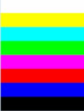
1. without image sensors, if I use the internal test pattern and output to 954, the test pattern is able to display correctly on the LCD display, something similar like below:

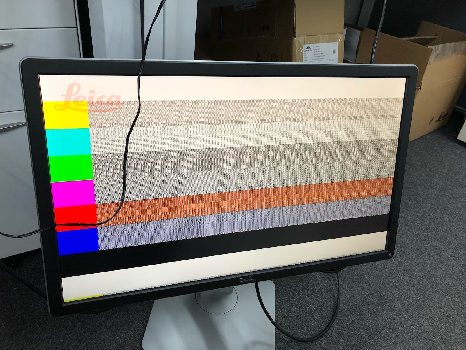
2. However, if I connect the my image sensor to the 953 and output via 954, I get the following output pattern distortion. The image distortion always happened at the same location. (please ignored the water mark behind the second line)

the white and black pattern are correct, only the test pattern in between white and black is having issue after it display correctly at beginning portion.

I don't think it is the hardware issue since the test pattern without image sensor is able to display correctly in step1.

Any expert can advise what could be the issue?

Best regards,

kpk

  • Hi Kpk,

    Can you please provide some additional information? What is the frame rate, resolution, and data type for the image sensor & the internal test pattern?

    Are you using Clk_out on the 953 to provide the clock for the image sensor?

    Can you please tell us the values of registers 0x5C, 0x5D, 0x5E, 0x5F, 0x60, 0x61?

    Thanks,
    Zoe
  • Hi Zoe,

    1. Can you please provide some additional information? What is the frame rate, resolution, and data type for the image sensor & the internal test pattern?

    Working at 1920x1080, 30fps, 10bit/12bit, activating 954/954 internal pattern generator we can get vertical bars, but when activating sensor test pattern sees attached picture where some portion of image is ok but the rest is noise/distortion.

    1. Are you using Clk_out on the 953 to provide the clock for the image sensor?

    Using in CSI-2 synchronous mode, refclk 24MHz at 954 side, at 953 side, the clock to sensor is measured at 24MHz also.

    1. Can you please tell us the values of registers 0x5C, 0x5D, 0x5E, 0x5F, 0x60, 0x61?

    953 i2c ser_id is 0x30 (0x5B), ser alias is 0x30 (0x5C)

    Sensor slave id 0 to 953 is 0x34 (0x5D), slave alias 0 is 0x34. (0x65)


    0x005B        0x30      SER_ID

    0x005C        0x30      SER_ALIAS_ID

    0x005D        0x34      SlaveID[0]

    0x005E         0x00      SlaveID[1]

    0x005F         0x00      SlaveID[2]

    0x0060         0x00      SlaveID[3]

    0x0061         0x00      SlaveID[4]

    0x0062         0x00      SlaveID[5]

    0x0063         0x00      SlaveID[6]

    0x0064         0x00      SlaveID[7]

    0x0065         0x34      SlaveAlias[0]

    0x0066         0x00      SlaveAlias[1]

    0x0067         0x00      SlaveAlias[2]

    0x0068         0x00      SlaveAlias[3]

    0x0069         0x00      SlaveAlias[4]

    0x006A        0x00      SlaveAlias[5]

    0x006B        0x00      SlaveAlias[6]

    0x006C        0x00      SlaveAlias[7]


    Best regards,

    kpk

  • Hi Kpk,

    Thank you for the additional information.

    For the registers, I actually meant those registers on the 953. Could you please provide that information? 

    Best,

    Zoe

  • At 953 side, the register values are :

    0x0050 0x20 REV_MASK_ID
    0x0051 0xC0 DEVICE STS
    0x0052 0x47 GENERAL_STATUS
    0x0053 0x00 GPIO_PIN_STS
    0x0054 0x00 BIST_ERR_CNT
    0x0055 0x03 CRC_ERR_CNT1
    0x0056 0x00 CRC_ERR_CNT2
    0x0057 0x00 SENSOR_STATUS
    0x0058 0x07 SENSOR_V0
    0x0059 0x07 SENSOR_V1
    0x005A 0x07 SENSOR_T
    0x005C 0x00 CSI_ERR_CNT
    0x005D 0x00 CSI_ERR_STATUS
    0x005E 0x00 CSI_ERR_DLANE01
    0x005F 0x00 CSI_ERR_DLANE23
    0x0060 0x00 CSI_ERR_CLK_LANE
    0x0061 0x12 CSI_PKT_HDR_VC_ID
    0x0062 0xD2 PKT_HDR_WC_LSB
    0x0063 0x00 PKT_HDR_WC_MSB
    0x0064 0xA4 CSI_ECC
    0x00B0 0x04 IND_ACC_CTL
    0x00B1 0x4A IND_ACC_ADDR
    0x00B2 0x3F IND_ACC_DATA
  • Hello Kpk,

    Thanks for the additional information. I see that the data type listed in register 0x61 is 0x12, which is generally not used for image data. If this is just for a few lines to provide additional information, this should be fine. Can you check if this is consistently the value in this register?

    Normally, I would expect to see a datatype of 0x2B or 0x2C for RAW10 or RAW12 data. There may be some issue with the image sensor configuration.

    Regards,
    Zoe