


Part Number: DP83822I
Dear Specialists,
My customer is considering DP83822.
He'd like to confirm how to use LED_0.
I would be grateful if you could advise.
---
Could you please confirm my understanding.
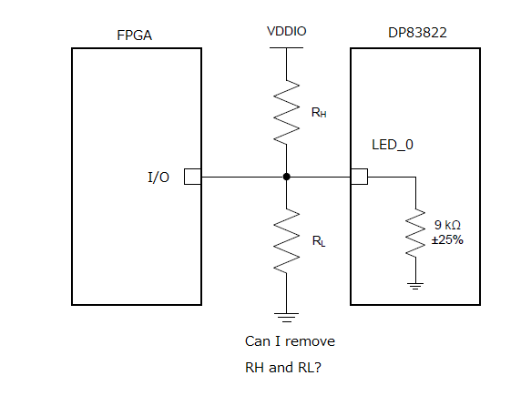
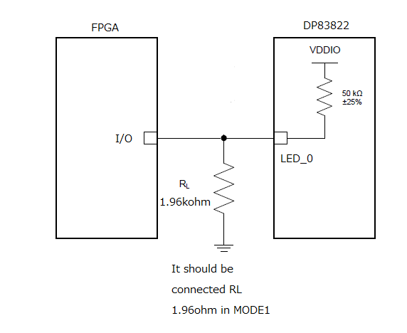
(1)LED_0 has an internal pull-down resistor only, there is not pull-down resistor.
(2)LED_0 can connect to logic device like FPGA.
In this case, I think it doesn't require pull-up or pull-down resistor.
Because LED_0 isn't for LED lighting.
Is this correct?
(3)LED SPEED of Table 13. is LED_1 control of 0101(100Base) or 0110(10Base) of LEDCFG(bit 11:8)
(4)If LED_0 is ON , logic H is output.
Also polarity can be changed by LED_0 Polarity.
---
I appreciate your great help in advance.
Best regards,
Shinichi
