Part Number: DS90UB954-Q1
Hi team,
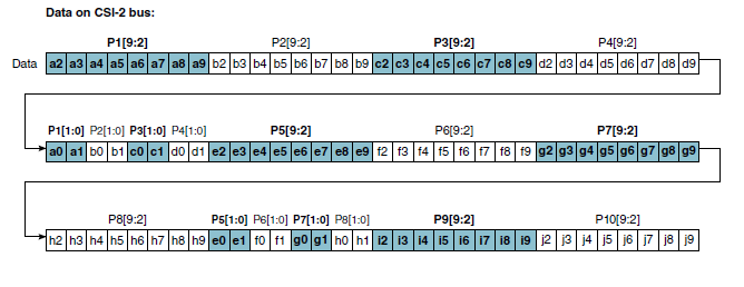
Our customer will use 954 as RAW10 mode connected 913A.
Please tell me the correlation between the YUV input data of 913A and the data array of the output in RAW10 mode of 954.
Best regards,
Tomoaki yoshida
Part Number: DS90UB954-Q1
Hi team,
Our customer will use 954 as RAW10 mode connected 913A.
Please tell me the correlation between the YUV input data of 913A and the data array of the output in RAW10 mode of 954.
Best regards,
Tomoaki yoshida