This thread has been locked.

If you have a related question, please click the "Ask a related question" button in the top right corner. The newly created question will be automatically linked to this question.

TPS2065C: Burned out!

Part Number: TPS2065C

Hi,

Consider 2 identical non-isolated (common ground) dcdc converter (say C1 and C2), and 2 TPS2065C groups (say A and B). Vin of A and B are C1 and C2 respectively. The A group is enabled by C1 as usual, but may I enable B with C1 as well? Indeed, in one of our prototypes, I’m burning out all B and no A parts. Can this be the cause? BTW, I have done this before without any problem until now.

Thank you!

Wolfgang

  • Hi ,
    Could you uplaod your schematic for fully undertand ? Are these two TPS2065C broken in your application ?
    You should care all the parameter should within device SPEC.
  • Hi Michael,

    Thank you for your response, and please apologize for my delay I’m quite busy these days; even so we made several tests for better understanding the problem. Follows our partial or preliminary conclusions.

    First some background of our design. Few years ago, we developed a base board (or motherboard) for one of our project which includes 2 dcdc converter 12/5 VDC and up to 5 switches (last release). The current release of the board is the 4th generation, which experienced the – burned out – switches (more precisely 3 of 5 switches are burned out, we guess, by our application, no standalone test was performed). We never experienced problems with switches before.

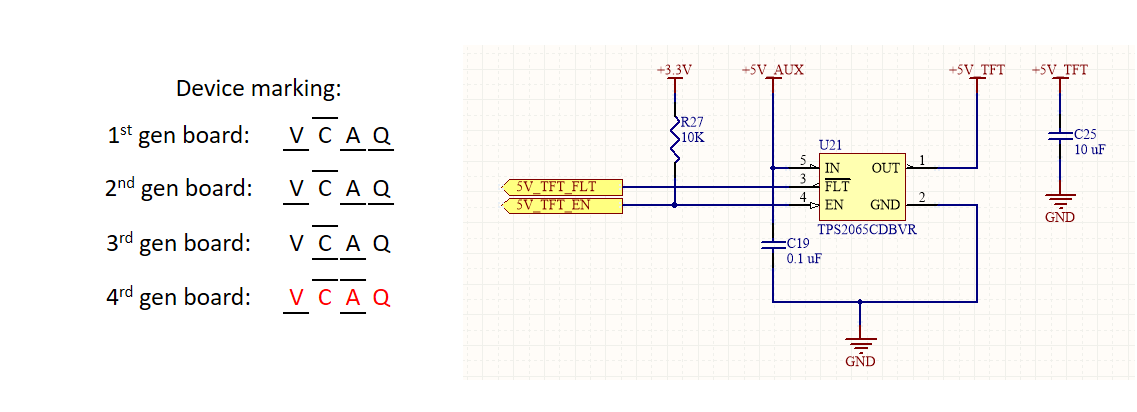
    For device marking and schematic of one switch, please see attachment (in red device marking which burned out). Output load are passive (no source is connected to the output), FLT and EN signal are handled by the micro controller @ 3.3 V; DCDC converter are a Murata 12/5 VDC, 1.5 A max current output.

    Test bed (standalone, no micro controller used): We select 1 switch on the 3rd and 4th generation board (layout/footprint of PCBs are identical). The enable signal used for test purposes comes from the same source of Vin @ 5 VDC. We used an already in production 3rd generation board and a brand new 4th generation board.

    • Under 0.7 A current load. Both generation boards behave well (on/off and temperature are normal), no difference between these two generation boards are noticed. Test duration about 1 hour each.
    • 0.8 A current load.
      The switch on the 3rd generation board behaves well; package temperature is normal (no special heating is noticed touching the package).
      The switch tested on the 4th generation board becomes extremely hot (you can´t touch it for more than a few seconds), switch features on/off behaves normal, overall power consumption increases 1W in comparison with the 3rd generation board using the same configuration. Test duration was about 30 seconds on the 4rd generation board (we don´t trust the thermal shutdown).
    • Constant-current mode test (output load exceeds 1A).
      Both – switches – behaves normal, limiting current to the threshold, but the switch on the 4th generation board remains extremely hot, consuming about 1W more power.
    • Short circuit test. Not performed.

    Preliminary conclusion: The use of our application continuously demanding more than 0.7 A in a switch will fry it sooner or later. Could be some - out of specs -  on θJA or RDS(ON), related specifically to this specific die series? 

    We are preparing one board for continuous testing 24x7, limiting current load of any switch to 0.7 A. 

    Thank you for your support, best regards, 
    Wolfgang

  • Hi Wolf,
    Sorry for reply late! As you mention you have do the comparision test between Gen3 and Gen4 and found the Gen4 power swith more hot than Gen3. Do you have thermal test result for analysis?

    I suggest you use the Gen 3 sample to replace Gen4 to double confirm it is not the PCB board and external component issue(PCB Cu thick will impact heat dissipation ).

    Michael.Tan
  • Hi Michael,
    thank you for your reply.

    Even if we hope so, we asked our assembly company if both PCBs (4rd and 3rd gen) are of the same type and quality, and still waiting they response.
    Unfortunately, we have no facilities to do a formal thermal analysis of the chip; In the next days, we would try to install a former (old) switch on the new board. As soon as we get this done, we will let you know our results.

    Best regards,
    Wolfgang
  • Hi Woody,

    It's been a while since we've heard from you. I'm going to go ahead and close this thread, but if you have any other issues, feel free to re-post here or start a new thread.

    If this answers your question, PLEASE select  This resolved my issue