


Part Number: DS90UB953-Q1
Other Parts Discussed in Thread: DS90UB954-Q1,
Hi,
We are designing a pair of Serializer and Deserializer boards using DS90UB953-Q1/ DS90UB954-Q1 pair, for camera application using Power Over Coax.
Can you please clarify us the below queries regarding PCB layout.
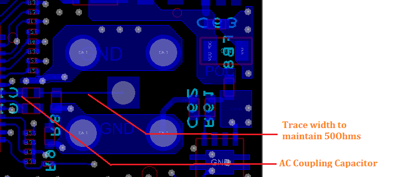
Q1. We are maintaining a trace width of 50 Ohms impedance for coaxial output signal to Serializer/Deserializer (SERDES) IC. But on connecting the same signal to PoC filter network, we could not maintain the trace width, as it needs to carry higher current.
Can the coaxial output signal trace width vary when connecting to PoC filter. Or is 50 Ohms trace width need to be maintained even for PoC filter input.
SERDES TOP LAYER:

SERDES BOTTOM LAYER:
SERDES TOP and BOTTOM LAYER:

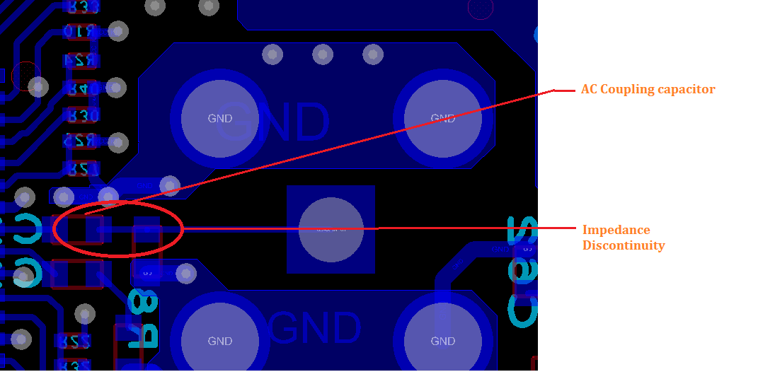
Q2. We are connecting the coaxial output signal to AC coupling capacitor near SERDES IC.
Is care need to be taken on PCB layout (eg: voids under capacitor) to avoid impedance mismatch.
You help is highly appreciated.
Thanks in anticipation,
Uma
