This thread has been locked.

If you have a related question, please click the "Ask a related question" button in the top right corner. The newly created question will be automatically linked to this question.

TINA/Spice/TPL7407L: Adding overcurrent protection around device

Part Number: TPL7407L
Other Parts Discussed in Thread: TINA-TI,

Tool/software: TINA-TI or Spice Models

Hello,

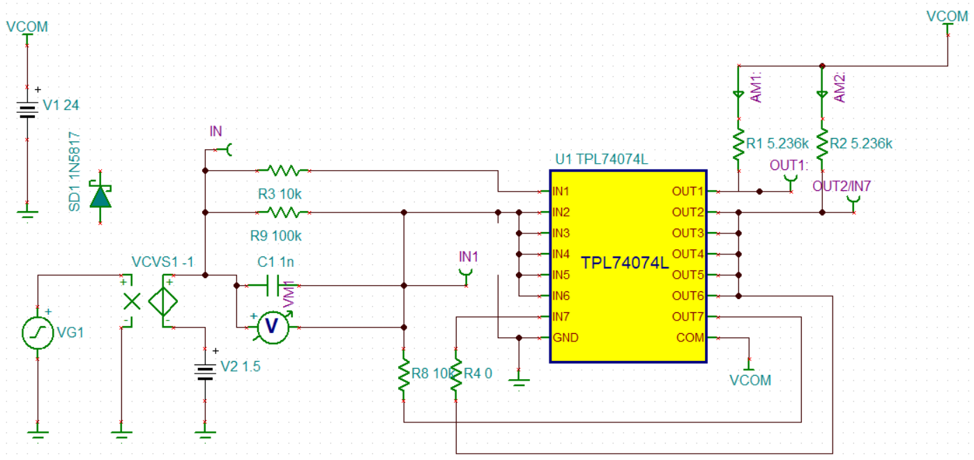
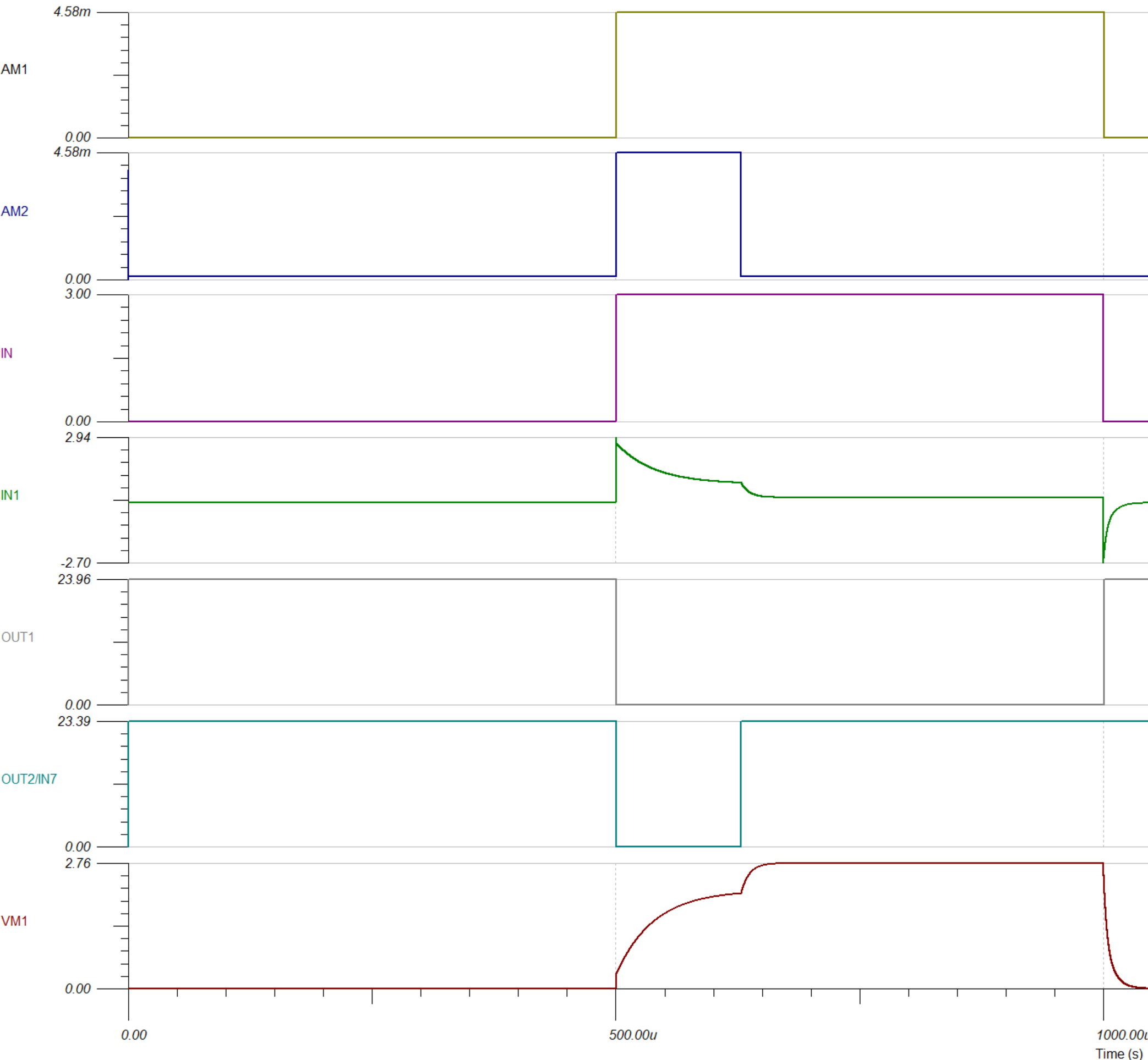
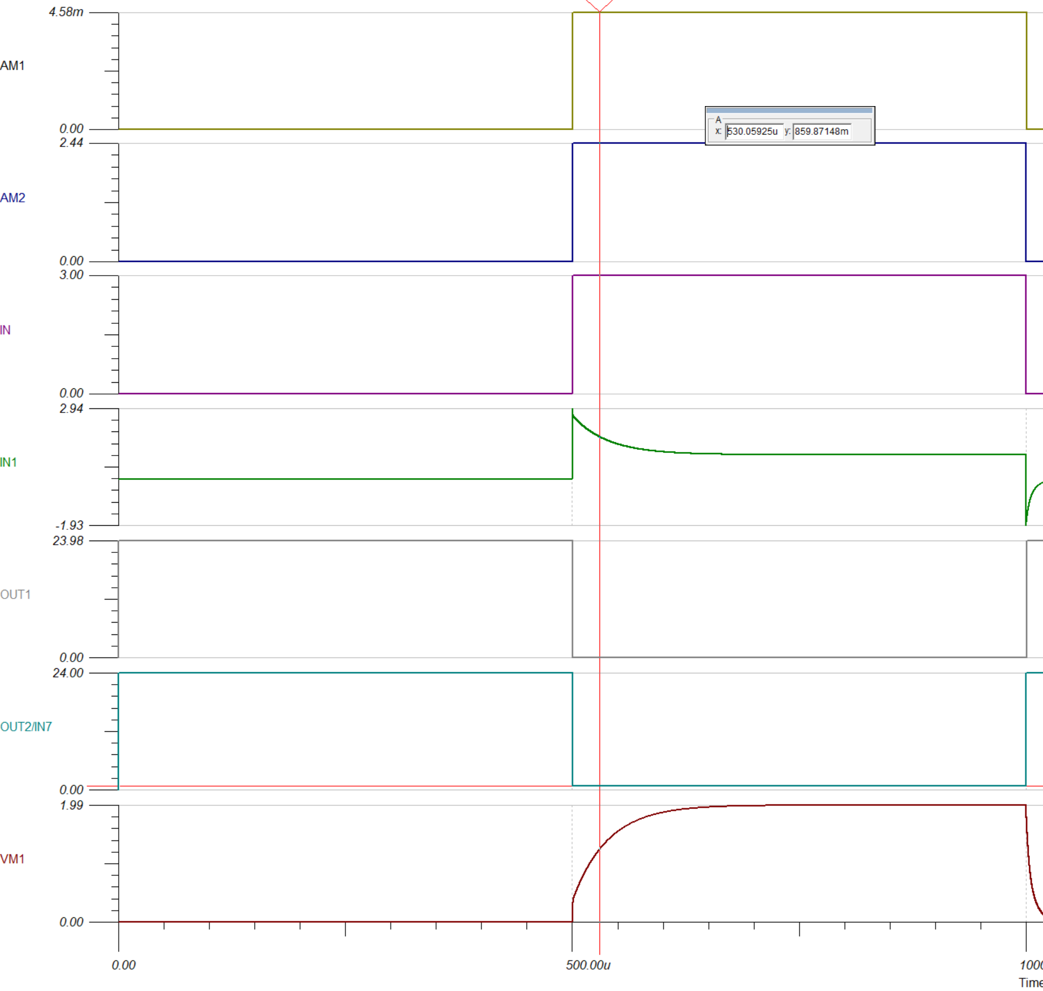
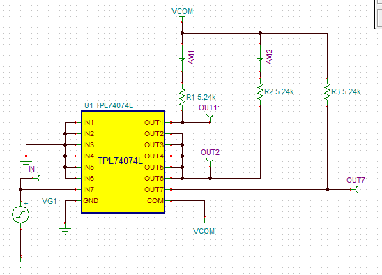
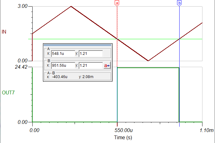
I was interested in using the feature described in App Note SLLA352 (Designing Overcurrent Protection for the TPL7407L Peripheral Driver) section 3.3 on self-protecting the driver.  After running simulations in TINA, I noticed that when the input switches off (from 3.0V to 0V), the voltage on the input pin for the self-protected circuit goes to -2.7V due to capacitor C1.  This seems out of line with the absolute maximums given in your datasheet of -0.3V on the input pin.  Won't the negative voltage damage the device?

The self-protection feature seems to fail in the TINA simulation above temperatures of ~35C.  Is this due to the model itself? The overcurrent circuit will trip every time no matter how small the load, so I don't think this is how the physical device would function if I were running it at, say, 60C ambient. 

  • Hi electronicjohn,

    The voltage on the input pin dropping down to -2.7V may be due to how quickly the input voltage drops down in your simulation, and this may be slower in your actual system. Either way, you are correct, the voltage should not drop below -0.3V to keep the device protected. The ESD diodes at the IN6 and IN7 pins would be put at risk since they would start drawing current below -0.3V. It is difficult to tell how the system will behave without testing it on actual silicon.

    As for the self-protection feature failing at 35C, could you please elaborate? Does the current trip threshold shift with temperature until it is out of range at 35C? I am trying to see what temperature shift may be built into the model for the device and why it is causing the OCP to stop working.

    Thanks,

    Alek Kaknevicius

  • Here is my schematic, based off of the TI WEBENCH reference circuit for the part. between the two plots below, I have changed the value of R2.  The first plot you see that at T=40C, R2=5.236k, the IN7 pin is being recognized as a "high" even though the voltage is only 91mV, and there seems to be multiple steps in the plots of IN1.  With the temperature reduced slightly to 35C, the trip point for IN7 is between 850-950mV, which I find more believable but is still quite different from the datasheet's specified minimum of 1.5V VIH

  • Hi electronicjohn,

    The trip threshold for the IN pin of the TPL7407L is actually between VIL and VIH. In this case, that would be between 0.9V and 1.5V. While 900mV would technically fall into this category, it is definitely on the low side of that range. What I don't understand is the threshold tripping at 91mV since this is definitely out of spec for the device. Let me assign this post to the modeling team to see why the IN threshold is so low at 40C and why temperature makes such a drastic difference here.

    Thanks,

    Alek Kaknevicius

  • John,

    As it turns out, some of the model's parameters are a little out-of-date since the data sheet went through a major revision after the model was released.
    I will review your findings with an eye towards updating the model to meet the current specs.

    I will have an update early next week.

    Regards,
    John

  • Thanks for the update, I look forward to it!
  • John,

    Apologies for the delayed response.
    It looks like this model is not intended to track the device behavior over temperature.

    You can see that in the text header of the model's netlist.
    You can access it by right-clicking on the symbol and selecting Enter Macro.
    The TPL7407L header has the following:
    ******************************************
    * Notes: This macro will conform to most DC parameters in the data sheet
    * for temp = 27C.
    * It may not track the data sheet behavior over temperature.
    ******************************************

    Temp behavior wasn't included because it was not requested by the supporting product line.

    Out of curiosity I looked at the input threshold on IN7 behavior using a modified version of your circuit:

    The source is a 1 kHz triangle waveform that swings between 0V and 3V. Looking at the existing model netlist confirmed the threshold is set to 0.9V, the MAX value of VIL.
    The model here was revised so the threshold was half-way between MAX VIL and MIN VIH = 1.2V The plot below shows the behavior. The output doesn't seem to change if the ambient temp is either 27C or 40C. If the threshold is set to the nominal value of 0.9V, the plots shift as you would expect, but they don't change for T=27C or T=40C. The test circuit with modified model is attached.

    I am not sure how to resolve what you are seeing with your circuit. If you wish, I can move the thread to the E2E forum that is supported by the product line's apps engineers. They will be able to help resolve the problems you are seeing. Please let me know what you would like me to do.
    Regards,
    John

  • Apologies John.
    I did not handle the images and upload correctly.

    The test circuit:

    The test circuit output with modified model input threshold, 0.9V changed to 1.2V:

    The test circuit should be attached this time.
    Regards,
    John

    tpl7407l_TB.TSC