This thread has been locked.

If you have a related question, please click the "Ask a related question" button in the top right corner. The newly created question will be automatically linked to this question.

TLK106L: strange TX waveform

Part Number: TLK106L
Other Parts Discussed in Thread: DP83822I, TLK105L
Hi!
We have an issue with the ethernet communication over the TLK106L.
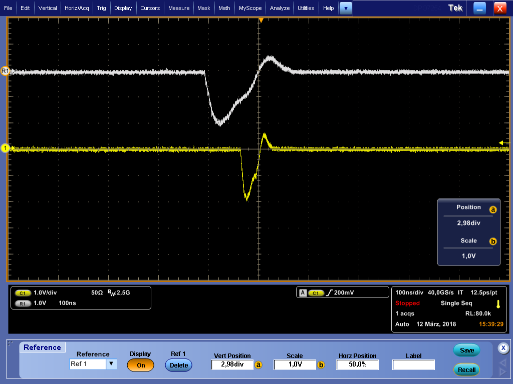
Our System works in normal operation. We cyclically ping the TLK106L. If we turn the ETH-Link off and on, it starts that we lost about 7%-10% of the pings. This can even happen sometimes, if we do not switch the link. While researching the problem, we consider the TX Signal of the ETH PHY. If we measure the RX and TX signal from the TLK106L, we can see a strange waveform on the TX signal. You can see the waveform in the attached file. The TX signal from the TLK106L shows a rippelvoltage with about 1GHz. Have anybody else seen this waveform with a TLK106L? Is this a known issue of the TLK106L, or an normal behavoir?
You can see that the Rippel is damped by the ETH Cabel. If we increase the length of the cabel, the signals gets even better, but this is expected.

Best regards
Kevin

TLK106L_TX_waveform.pdf

  • Hello Kevin,

    Would it be possible for you to share the schematics?

    -Regards,
    Aniruddha
  • Hello Aniruddha,

    thank you for your fast respond.
    I have attached the schematics from our TLK106L.

    For that I have some additional informations about what we have already done to improve the behavoir:
        
    a) We increase the cpacitors C900 and C901 to 1µF.                                 --> nothing changed
    b) We soldered 1µF parallel to C900 and C901.                                          --> nothing changed
    c) We soldered 4.7µF parallel to C900 and C901.                                       --> nothing changed
    d) We soldered 10nF parallel to R939 (RBIAS, just to try).                          --> nothing changed
    e) We soldered 0 Ohm instead of FB900.                                                       --> nothing changed
    f) We optimized the termination for G900 by changing R940 and  R941  --> nothing changed

    g) Our Transformer L900 is placed with the CMC to the side of the RJ45 connector. This is done because we have a PoE Device and use the CMC as Filter for the PoE Power Supply.
       In the Datasheet (SLLSEE3D) and the design guide SLVA531A the CMC is required on the TLK side. But the pictures of the schematics and the schematics of the TLK10xLEVM board, shows
       the CMC on the connector side.                                                                     --> which side is needed and why?
    h) with regrad to g) In the article DP83822I: Magnetics with choke on the side of the PHY the problem with the CMC is also addressed.
       It is also a problem with the link                                                                     --> we will try to rotate the transformer.

    i) In the article TLK105L: TLK105L - TX signal perturbations there seems to be the same Problem with the TX signal wave form.

    --> Is there an other solution than the DP83822? In parallel we will try to use the DP83822.

    Regards

    Kevin

    TLK106L.PDF


  • Just a quick update.

    h) I have changed the position of the CMC to the phy side. It did not improve the behavior regarding the ping and the waveform.

  • Hi,

    we have an update to the point i.

    we got some DP83822 and soldered it on the PCB. We have nothing further adapted on the Layout and the software.

    We can reach the device via the MDIO interface, but the DP83822 is not able to build up a link. In the atteched image (it is inverted because we pluged the differential probe in the wrong way) you can see the NLP, but is only about 50ns wide ( it should be 100ns wide, like REF1.

    If we look at the FLP burst, we can see the time between pulse positions is about 23µs insteatd of 62,5 µs.

    Is there any idee why the DP83822 seems to be operating to fast?

    Regards

    Kevin

  • Please ensure that if you are using MII, RGMII or RMII Master operation that you supply a 25MHz reference clock.
    If you are using RMII Slave operation the reference clock should be 50MHz.

    Can you please read register 0x467 using extended register access and let me know what the readout is?
    What mode of operation are you trying to operate in?
  • Hi,

    thank you for your answer, but we already solved the issue with the short link pulse.

    We are using RMII Slave with 50 MHz.. Because the DP83822 now supports 4 modes on the bootstrap pins, we got the wrong mode on the RX_DV pin.

    After we fixed this, we got the correct link pulse.

    Best Regards

    Kevin

  • Hi,

    is there an idea or approach for the TLK106L TD output waveform from TI?

    Best Regards
    Kevin