This thread has been locked.

If you have a related question, please click the "Ask a related question" button in the top right corner. The newly created question will be automatically linked to this question.

TPS2544: VBUS drop when connect with Apple product

Part Number: TPS2544
Other Parts Discussed in Thread: TPS2546

Dear Team,

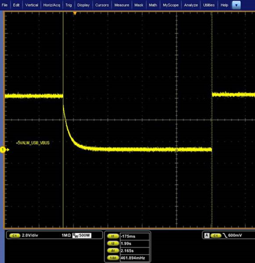
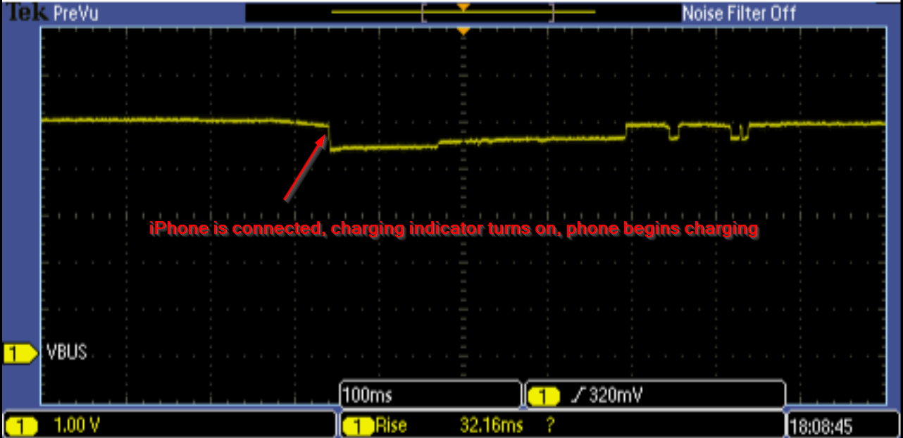
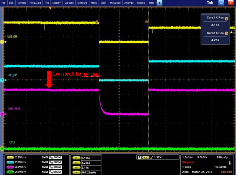
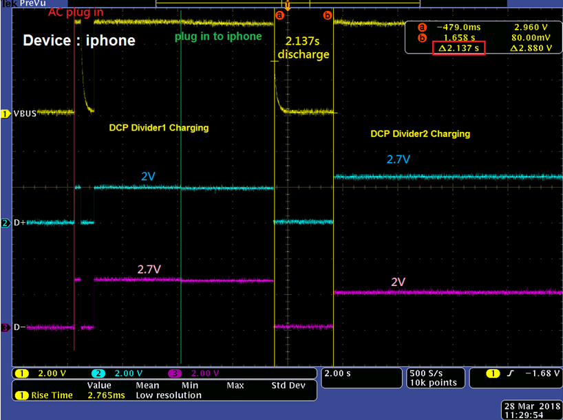
So far we found that TPS2544's VBUS will drop about 2 second and then go up again as below figure when it connects with Apple product. Ex: Iphone SE, Iphone 7.

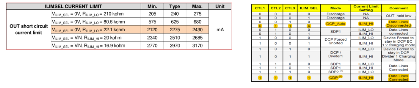
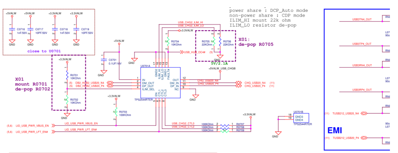
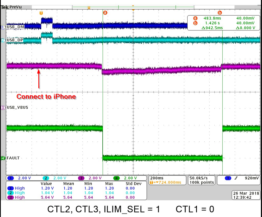
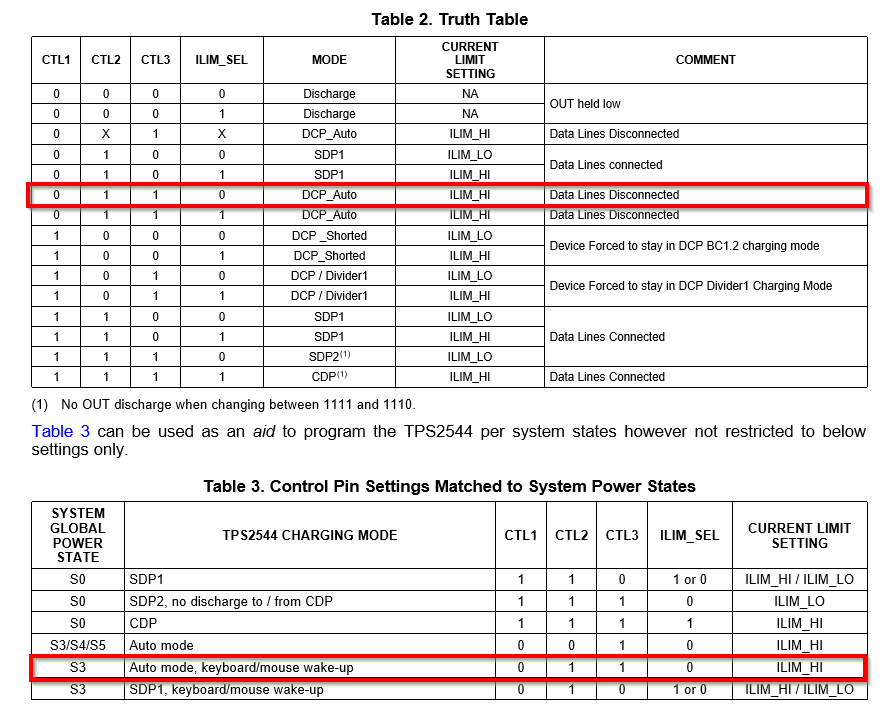
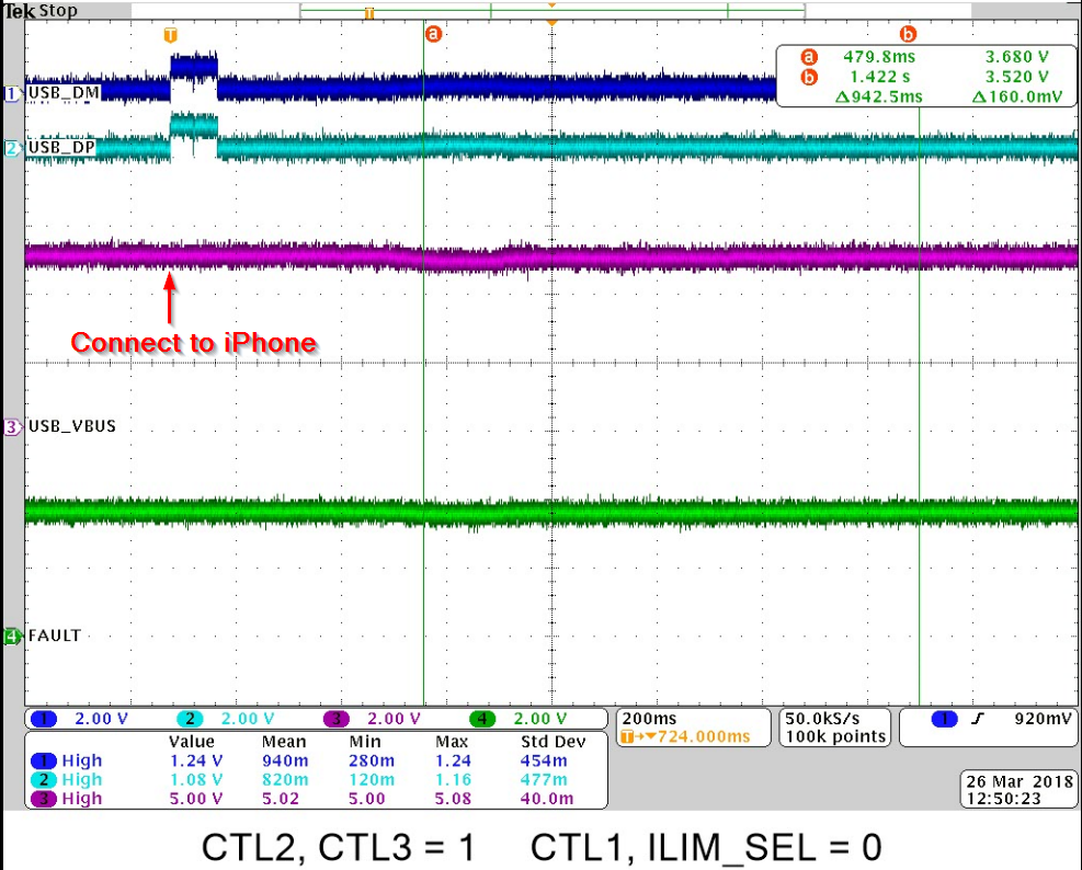
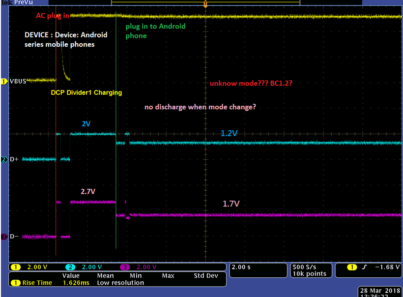
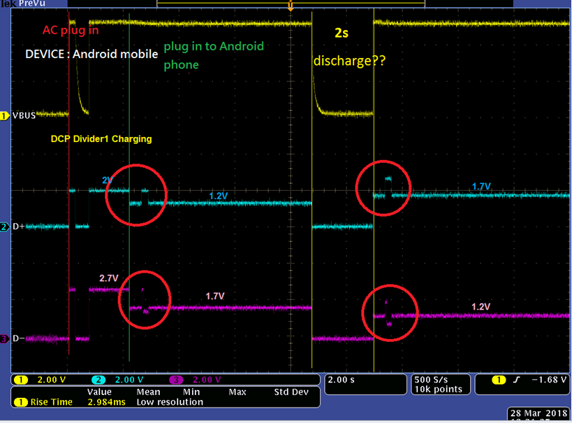
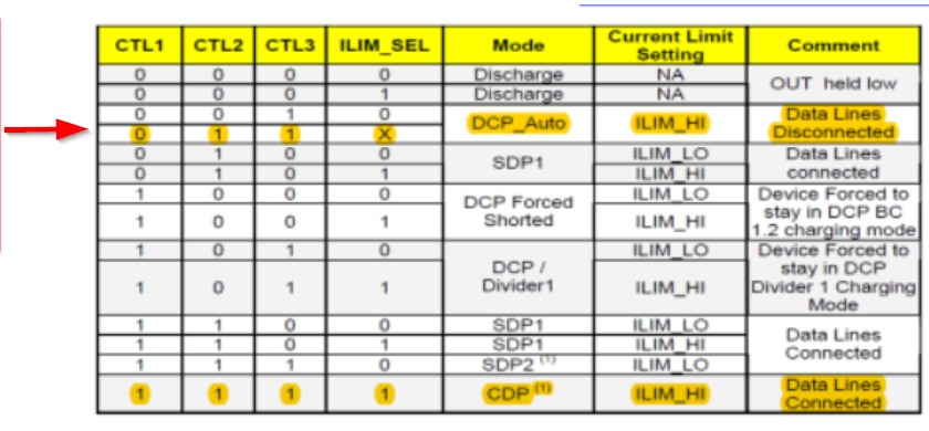
Is it related to the mode we are using? We only use DCP_Auto and CDP mode as below.


  • Hey Jim,

    Thank you for posting your question on E2E. I do not currently have any TPS2544EVM's to work on. I requested some from the TI store, and should get them next week, but until then all the debugging that I do will be either through you or using the TPS2546EVM. I apologize for any inconvenience this may cause you.

    First, how are you conducting the test to get this waveform? EX) is the iPhone already connected to the type A port, and then you turn on the power supply? Is the device on, and then you plug the phone into it? Or does it not matter what you do, there's this voltage drop regardless?
     
    Second, does this voltage drop happen during both DCP_Auto and CDP modes? And is the voltage drop and duration pretty much identical for each?

    Third, the division lines are kind of difficult to make out in the scope capture you sent. Is VBUS dropping to 0V?

  • Hi Adam,

    As I know, TPS2544 is almost the same as TPS2546. The difference is that TPS2546 suport the power saving feature.

    Sorry about that I didn't make it clear. About the waveform I captured follow the steps as below.

    Step 1: We saw that there is 5V on VBUS
    Step 2: Connect Type A port with Apple product.
    Step 3: VBUS drop about 2 second and go up again.

    Yes, VBUS drop to 0V, because TPS2544 turned of its MOSFET.

    Regards,
    Jim
  • Jim,

    You are correct on the differences between the TPS2544 and the TPS2546. The TPS2544 EVM's have not arrived so the screen capture below is from the TPS2546EVM.

    I put the board into DCP_Auto mode, based on the graph and highlighted sections you included within your previous post.

    Following the same setup and testing steps you described, I was unable to see a 5V to 0V voltage drop. Below is a screenshot of the waveform generated from VBUS. The voltage drop on VBUS is from the phone being connected and the chagre indiciator being displayed.

    I believe that our voltage drops are occuring at the same place, but for some reason, the FET tied to the output pin is being activated, so VBUS is being pulled to ground.

    I'll try this test again once the TPS2544EVM comes in to see if I get any difference of a response. In the mean time, would you be able to send me screenshots of the DP-IN and DM-IN lines when the iPhone is initially connected to the phone? Curious to see if there is any problems there.

    Also, would you be able to email me a full schematic? Want to see where some of these off page references are going to.

  • Dear Adam,

    I have sent you the schematic and waveform by mail.
    Please help to take a look.

    Thank you.
    Regards,
    Jim
  • Hey Jim,

    After doing some research this is normal behavior. Following the BC1.2 specification, VBUS must drop when changing between CDP mode, DCP mode and SDP mode.

  • Hi Adam,

    There is no any mode change when plug in Apple product.

    Default value of CTL2, CTL3 and ILIM_SEL are high.

    The mode change only occur when the system enter S4 (CTL1 from 1 to 0) or resume to S0 (CTL1 from 0 to 1).

    As you can see below, CTL1 was always low when the system is in S4.

    Please help to clarify the issue.

  • Jim,

    The TPS2544 EVMs finally came in so I was able to do some tests using that part. I configured the part similarly to how y'all had it configured (CTL2, CTL3, ILIM_SEL = 1 ; CTL1 = 0) and did not see the VBUS drop like the one y'all saw. I do not think the problem is internal to the TPS2544, but instead how y'all are implementing it since VBUS works fine on the EVM.

    I did notice though that the FAULT LED lights up randomly when the iPhone is connected to the EVM. Is the FAULT pin connected to an MCU somewhere else within the design that enables or disables the TPS2544? This may be causing the voltage drop issue that you are seeing. I took a scope shot of the FAULT pin during the initial connection, and the time when the FAULT pin goes low is almost identical to when VBUS drops for you.

    Can you try to disable the FAULT connection to see if this is the root of the issue?

    Second, I tested to see if there are any other modes that allows for iPhone charging, is in S3, and does not have the FAULT pin go low. The following configuration from the truth table meets all three conditions. Try configuring the TPS2544 in this configuration and see if it solves the VBUS drop issue.

  • Dear Adam,

    The waveform we captured as below. It seems like the root cause if not related to FLAULT pin or EN pin.

    Plug-in Device: iphone

    CH1: VBUS (pin12)

    CH2: +5VLAW (pin1)

    CH3: EN (pin5)

    CH4: FLAULT# (pin13)

    But we found the description of DCP auto on the datasheet as below. So once the charging current more than 750 mA, TPS2544 will switch to Divider 2 and cause VBUS drop. And we also captured the waveform as below.


    And we also test it with Android mobile phone and found that there are two kind of conditions.

    Android Condition 1: 

    Based on below waveform, it seems like TPS2544 change from Divider 1 to BC1.2 mode, am I right?

    Do you know what kind of mode will present 1.2V on D+ and 1.7 on D-?

    Android Condition 2:

    Condition 2 is similar to the condition 1, but it did the discharge and present 1.7V on D+ and 1.2V on D-.

    Does it means that TPS2544 enter another fast charge mode?

    Do you know how to explain the waveform in below red circle? Is it the 1.2V mode? 

    Thank you.

  • Jim,

    Great catch. Yes, that is exactly what is happening. The device is starting in Divider 1 mode and changing from there based on the current draw or device detection on the other end. And since the modes are technically changing, VBUS drops accordingly. However, we weren't able to replicate the issue of having the D+/D- lines be at 1.2V/1.7V.

    What type of Android phone is being used? Also, would you be able to send us screen captures of the current coming out of VBUS throughout these tests? Will help us to determine what mode this device is in

  • Hi Jim,

    TPS2544 does not have 1.2V/1.7V mode, it should be 2.0V/2.7V.  But it is possible you observe 1.2V/1.7V after connecting smartphone because some smartphones will pull D+ and D- low. This is smartphone behavior.

    regarding your waveforms , android condition1 should be 2.0V/2.7V mode, because the load current did not exceed 750mA, TPS2544 stayed in 2.0V/2.7V mode and did not discharge.

    android condition 2, TPS2544 switched from 2.0V/2.7V to 2.7V/2.0V and discharged VBUS.