This thread has been locked.

If you have a related question, please click the "Ask a related question" button in the top right corner. The newly created question will be automatically linked to this question.

SN65DP159: DP159 AN: Termination Scheme

Part Number: SN65DP159


I need help to understand Application Report (SLLA358) DP159 as DisplayPort Retimer.

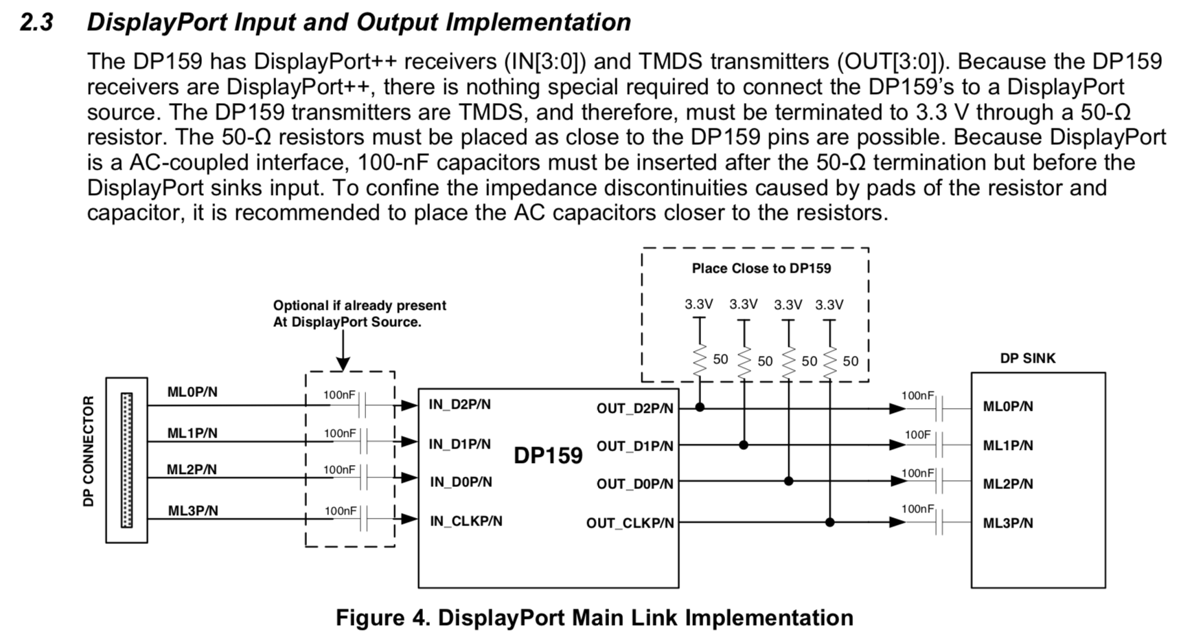
In section 2.3, "The DP159 transmitters are TMDS, and therefore, must be terminated to 3.3 V through a 50-Ω resistor." Why 50 Ohm pull up is required? If the trace characteristic impedance is also 50Ohm, then the 50 Ohm pull up plus the trace impedance will form a 25 Ohm impedance?

Why DisplayPort doesn't require this 50 Ohm and only a 100nF is sufficient? What is the difference between HDMI and DisplayPort in terms of this 50 Ohm pull up resistor requirement?

Thank you.

  • TMDS uses current mode logic to transmit data. meaning that the DP159's output data lanes needs a pull up resistor of 50 ohms to 3.3 V on the data lanes in order to pull current and create the AC voltage signal. the 100 nF allow the AC signal to go from the DP159's TMDS output to a DP output. DP does not require these resistors because the input to DP is not TMDS. HDMI uses TMDS for communication so most HDMI devices will have the 50 ohm pull up resistors internally at the input of the device.
  • Thank you for you response.
    The trace impedance after 100nF at DP SINK in the picture is 50 Ohm, will this trace impedance together the 50 Ohm pull up resistor form a voltage divider? So the total load impedance to DP159 output will be 25 Ohm?
  • You are correct in that the total load impedance will be 25 Ohms but not because of the 50 Ohm trace impedance, but because of the 50 Ohm termination resistor on the DP sink. This means that the output swing of the device will be half of what it would be under regular conditions. To overcome this the device can boost the output by changing the VSADJ pin like in Section 2.4(www.ti.com/.../slla358.pdf). Also the output swing can be increased by changing the registers on page 37(www.ti.com/.../sn65dp159.pdf) to increase the data and clock swing by 21%.
  • Thank you for helpful illustration.  Does LVDS also have 25 Ohm because of termination resistors?

    I am reading a paper from TI: "http://www.ti.com/lit/ug/snla187/snla187.pdf"  I understand the structure of TMDS vs LVDS now. What will the impedance be for LVDS in applications with and without AC coupling capacitors on datalines? For example, USB has AC coupling capacitors, the following example doesn't have AC coupling capacitors, will the total impedance be different in these two LVDS cases?

    Thank you.

  • The AC caps are there to block DC signals, with the frequencies that the signals are transmitted at the AC caps act as a short circuits and do not change the impedance of the lines vs the impedance of the lines without the caps.