This thread has been locked.

If you have a related question, please click the "Ask a related question" button in the top right corner. The newly created question will be automatically linked to this question.

Linux/TPS65986EVM: Muxes Not Correctly Configured/Debug Mode Settings

Part Number: TPS65986EVM
Other Parts Discussed in Thread: DP-EXPANSION-EVM, TPS65982, TPS65981

Tool/software: Linux

Hello all,

Have a question coming in from a customer, let me know if this is able to be answered or needed to brought to the product line's attention.

"I am currently bringing up a TPS65986 USB-C front end for a project.

I have gotten the basic functionality to work for USB 2.0 and 3.0 signaling.

At this time I am trying to get alternate mode working. I have tested the dev board with a DisplayPort dongle to make sure that my configuration is correct. Then I have switched over to another design design.

The design uses USB-C receptacle, and then internally drives a DisplayPort re-timer followed by DisplayPort receiver. The re-timer and receiver were verified to operate when the connection was previously made to thunderbolt port.

when I connect I can see hot plug detect light go on the Ti development board, but no high speed traffic is generated. It looks like the muxes are not configured correctly.

I have attempted to download debug information from our USB-C side, but our I2C address is not at 0x38. Is there a way to change the debug mode setting. I have tried to do it in Debug->Configure I2C/SPI Adapter Settings, but the value for I2C address does not stick."

Please let me know if this able to be answered given the information and I can ask the engineers for more information if necessary.

-Craig 

  • Hi Craig,

    I’m sorry you’re having issues. I have a few questions for you, which will better help me solve this issue.
    1. Is the customer using the TI DP-Expansion-EVM to test with the TPS65986EVM?
    2. Is the customer using a FTDI board to flash firmware to TPS65986?
    3. Is the customer using the TPS6598x Configuration Tool instead of the Host Interface tool for the GUI?

    One possible reason why the mux is not mapping correctly could be that the GPIO mapping of events for alternate mode might not be mapped to the correct high speed mux pins. Please reference the User’s Guide for both the TPS65986EVM and the DP-Expansion-EVM for proper hardware connections. Let me know if you have any further questions or concerns.

    Hao
  • Hi Hao!

    Thanks for the response.

    Here are the specifics:

    1) I am currently using Ti DP-expansion EVM as the source. I have made sure that the EVM works by using off the shelf USB-C to DP adapter. It is running factory code.

    2) I am using AArdwark to flash the board with no problems. I can also monitor the debug information on EVM with AArdwark with no problems.

    3) I am using the configuration tool.

    Thanks,

    Craig

  • Hao,

    Please see my responses from the customer and if you can further assist with the following issue:


    "I have the debugger up and running on our receiver side. I could use some help to get the Display Port up and running."

    Thanks!

    Craig
  • Hi Craig,

    Sorry about the repeated picture.

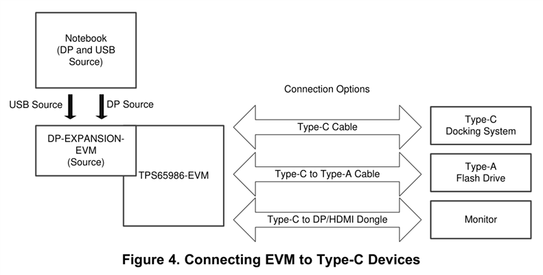
    For the DP function, try to use the connection topology in figure 4 of the DP-EXPANSION-EVM User Guide (look below).

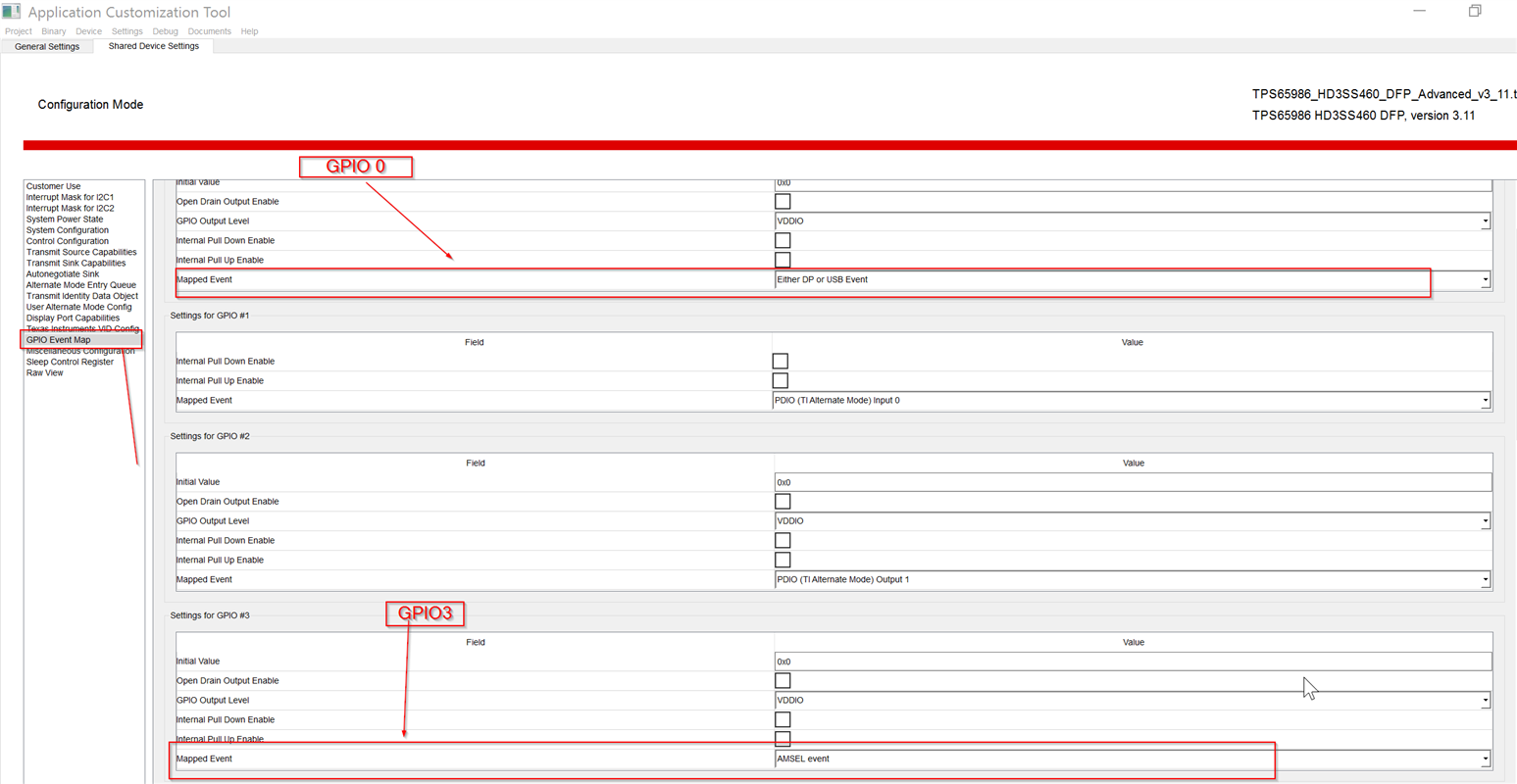
    The GPIO DP event mapping might be incorrect. Could you make sure that the setting of GPIO0 is mapped to “Either DP or USB Event”, and GPIO3 to “AMSEL event”.

    Also, you should make sure that the Display Port Config matches the screenshot below.

    FYI, the DP expansion has a passive HS mux, if the cable is too long, it may have signal integrity issues. Thank you for using our parts in your design.


    Best Regards,

    Hao

  • Hi Hao,

    Thank you for the response.

    I have a few more questions coming in from the customer:

    They are working on the receiver side, is the port capability correct? DPF_D only?

    and

    What checks are done to establish display port connection in register 5f?

    Thank you for the help!

    -Craig
  • Hi Craig,

    I have a few questions for you, which will better help me solve problems.
    1. What's the customer's connecting structure in "DP-EXPANSION-EVM User's Guide"? Figure 3, Figure 4 or Figure5?
    2. As for register 5F, please refer to "TPS65981, TPS65982, and TPS65986 Host Interface Technical Reference Manual", which has the detailed description of every bit.
    3. Did you follow the steps I have answered? If you are able to display to monitor, the alternate mode would work well.
    4. What does "receiver" mean you mentioned above? Source, sink,UFP, DFP, UFP_D, DFP_D, DRP?

    Best Regards,
    Hao