This thread has been locked.

If you have a related question, please click the "Ask a related question" button in the top right corner. The newly created question will be automatically linked to this question.

AM26LS32AC: AM26LS32AC

Part Number: AM26LS32AC

Hi,

I am using AM26LS32AC for encoder interfacing. I am using 100 ohm resistor for termination. But sometimes I didn't get output from chip. This problem resolved with multiple solution. They are as follows -

1 . If I change this chip with another one then my problem get resolved. Why this variation occurring from chip to chip? 

2.  I change termination resistor from 100 ohm to 200 ohm then this issue resolved. But as per your suggestion it should be in between 80 ohm to 120 ohm. What should be resistor value? If 200 ohm used then what will       happen?

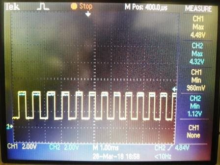
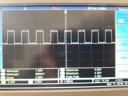
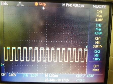
I have attached input waveforms to AM26LS32 for your reference.

Thanking you.

Regards,

Somnath barge

  • Barge,
    Thanks for reaching out to us. Where did you put the termination, between A and B pins? Your signal doesn't look quite right to me. If you take the difference between A and B, most of time it's zero and the difference is very small. AM26LS32AC has the threshold 200mV. You want your input signal (A-B) large than that to be a valid high. You can refer to Figure 5 of www.ti.com/.../am26c32.pdf for normal application waveforms.
    Please let us know if you have more questions.
    Regards,
  • Hao L,

    Thanks for reply. 

    I have attached my schematic for your reference. 

    If difference between A and B is less than 200mv then it shouldn't work to any 26ls32 chip. But this is not case. If I replace it with another one then it works. Why this happening?

    Thanks and regards,

    Somnath Barge26LS32.pdf

  • If the differential voltage is less than 200mV, it's gray area. The receiver could take it as a high or low. Therefore we don't want the device to work in that region.

    I'm not sure what the purpose of pull up resistor of B line (like R91) is. Usually people put pull up on A and pull down on B to generate a fail-safe voltage when the bus is idle. BTW, it looks like the connection of port 3 is reversed from the other two.

    I also think 100Ohm serial resistors (like R69 and R70) are too much. They divide the input voltage making the voltage drop on the termination resistor smaller.

    Regards,

    Hao

  • Hao,

    I checked by removing serial resistor but no luck.

    I put pull up resistor to B line so that there will be 2.5V if no signal present on B line. If I connect single ended encoder(only A signal present), then input A signal will compare with 2.5V.

    And this problem is coming to single ended encoder only. So how to resolve this issue?

    Thanks and regards,

    Somnath Barge.

  • Somnath,

    I'm sorry I still don't fully understand your application. Is your input signal a differential signal? Or is your input signal two single-ended signal? If you wanted to compare A signal to a 2.5V DC voltage, why did B signal toggle the same time as A signal in the waveforms? You can find typical RS485 signal in this page (http://www.alciro.org/alciro/RS-485_16/Lineas-RS-485_131_en.htm).

    Regards,

    Hao

  • Hi Somnath,

    I'm also curious why the B line seems to be tracking the A line. Can you please tell us how you are generating the 2.5-V reference? If this is created by a voltage divider using high resistances, then it only weakly bias the B line. In that case, using a low-resistance termination between A and B would make the B voltage track A much more closely than it tracks the reference. If this is the case, then the solutions may be to terminate A to ground rather than to B, to remove the termination (if not needed for signal integrity), or to more strongly drive a 2.5-V reference to the B input.

    Max
  • Hi Hao and Max,

    Thanks for reply.
    Actually I want to make universal circuit so that I can connect differential as well as single ended input signal. I am using this circuit from last few years and working fine. Differential signal is with 180 degree phase shift and therefore there is no issue. Only issue I am facing that sometimes it is not working for single ended input signal. At that time I replaces chip 26ls32 with another one then it starts working.

    To resolve above issue I increased terminating resistor from 100 ohm to 200 ohm instead of chip replacement then also it works. Only I would like to know by increasing terminating resistor to 200 ohm, will it affect on performance when differential input signal is given?

    Thanks and regards,
    Somnath Barge
  • Somnath,
    It's not common to use differential input with single-ended signal? Can you give little bit more details about your scenario in that case? Is your single ended input A pin? How about B pin? Do you want to compare the signal between A and B?

    You need to evaluate the differential signaling if you want to evaluate the impact of increasing the termination from 100Ohm to 200Ohm. For example, what's the cable's characteristic impedance? How long is the cable? What's your data rate? You can refer to this app note (section 6 on page 3) (www.ti.com/.../slla272c.pdf) for some details.

    Please let us know if you have any other questions.
    Regards,
    Hao