Hi,
I have asked the same question on the C5000 ultra low power DSPs forum. Since I don't know what is the appropriate forum to ask this question and because this matter is mainly related to the USB port, I've created this new thread.
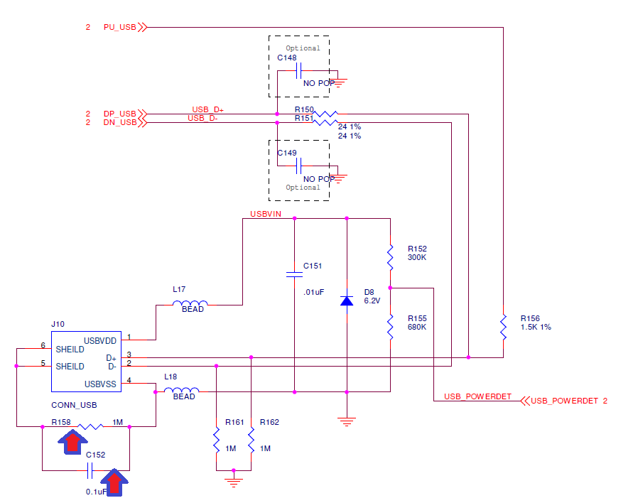
Why this resistor and this capacitor is used in the image bellow?
This image is taken from Spectrum Digital DSK5509A schematics. J10 with 6 pins is a USB socket and the nets USB_D+ and USB_D- are connected to TMS320VC5507 usb pins.
Thanks,
Hossein


