This thread has been locked.

If you have a related question, please click the "Ask a related question" button in the top right corner. The newly created question will be automatically linked to this question.

DS250DF210: PRBS Pattern Gen/Chk

Part Number: DS250DF210
Other Parts Discussed in Thread: DS125DF1610, , DS250DF410

Hello,

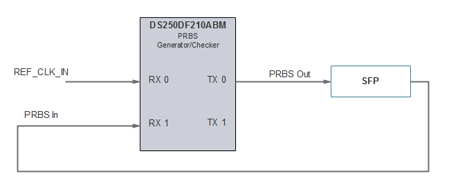
Our customer would like to add a cable tester to their design.  Using the DS125DF1610 BERT Tester Reference Design as an example, we would utilize the PRBS Generator of one channel of a DS250DF210 and the other channel use as the PRBS Checker .  Below is a diagram the basic concept.

We assumed that the PRBS GEN/CHECK core is similar if not the same as used in the DS125DF1610.

In our experience with the DS125DF1610 the following is true:

a.  You cannot operate the Generator and Checker on the same channel simultaneously

b.   You must have an input signal that is a factor of  a multiple of 2 of the desired line rate on the Generator's input in order for the Generator to create a pattern that can be checked by a PRBS Checker.

We have the following questions:

1.   What are the limits of the multiples of 2 of the desired line rate that must be present on the input in order for the PRBS Generator to operate at Line Rate?

2.   Our customer's maximum data rate is 10G Ethernet.  Is there a common Reference Clock Rate that could allow us to test both 10GbE and 1GbE without changing the REF_CLK_IN Frequency?

3.   The Crosspoint Switch aside, Is there an advantage of using the DS250DF410 over the DS250DF210 in this particular application?

  • 1.   What are the limits of the multiples of 2 of the desired line rate that must be present on the input in order for the PRBS Generator to operate at Line Rate?

    On the DS250DF210 if the input pattern is 1010 clock pattern the retimer can achieve lock for input data of divide by 2, 4, 8, and 16.

    2.   Our customer's maximum data rate is 10G Ethernet.  Is there a common Reference Clock Rate that could allow us to test both 10GbE and 1GbE without changing the REF_CLK_IN Frequency?


    The REF_CLK_in does not actually feed into the high-speed data path. This clock is used as a reference for digital core. On the DS250DF210 there is a standard channel register 0x2F setting for 10GbE rate. The DS250DF210 does not support 1.25Gbps in retimed mode. The user may operate in 1.25Gbps rate by setting the retimer channel to CDR bypass mode.

    3.   The Crosspoint Switch aside, Is there an advantage of using the DS250DF410 over the DS250DF210 in this particular application?
    I don't think there is a significant functional benefit. It's purely a channel count difference.

    Cordially,

    Rodrigo Natal

    HSSC Applications Engineer

  • Thanks Rodrigo

    Regards,
    Jack
  • Hi Rodrigo,
    Can you provide a link to the NDA request page for the DS250DF210 Programming Guide? This document is referenced all through the datasheet but I cannot find it online. I presume it is protected by an NDA.

    -Jack
  • Hi again Rodrigo,

    Just so that I'm clear on this. If we put a 644.53125 MHz (10G/16) differential clock signal on the RX0 input to the DS250DF210, we can get a 10.3125 GHz PRBS signal out that can be checked by the same device on the other channel?

    What registers would require "tweaking" in order for this to happen?

    -Jack
  • Hi Jack,

    Please request the document by clicking on the "Request for Information" link on the DS250DF210 product folder page.

    www.ti.com/.../DS250DF210

    Regards,

    Lee

  • Thanks Lee,
    Got it.

    Now I see where/how to configure for PRBS Generation and Checking and where default line rate of 10.3125 GHz is set (Table 24).  However, I'm not seeing where or how a 644.53125 MHz signal on the RX input leads to a 10.3125 GHz PRBS output.  I only see step 7 in Table 25: Set Data Rate.  None of these settings are /16.  The datasheet also states that the CDR will not lock to anything below 5.15 Gbps.  I'm perplexed.

    -Jack

  • Hi Jack,

    644MHz Clock is used by the internal PRBS generator to serialize internal PRBS bit stream generator.

    Regards,,nasser
  • Hi Nasser,

    Thanks for getting back to me. My apologies for somewhat repeating the questions, but It is critical that I confirm the intended functionality before we commit $$$ towards a prototype build.

     Below is my current understanding. Can you please confirm ( block diagram shown in the first post):

    1. The DS250DF210 will generate a 10Gbps PRBS output ( differential TX0 lines ) by:
      1. Connecting a 644.53125 MHz  clock source (101010 data pattern) to its RX0 differential input.
      2. Configuring the CDR for a default line rate of 10Gbe (10.3125Gbps)
    2. This PRBS stream can be checked by the 2nd channel of the DS250DF210 or by any device capable of checking PRBS of the same data rate and pattern, i.e. PRBS31.


    Regards,

    Jack

  • Hi Jack,

    Yes this is possible. If you send in a 644.53125 MHz signal, then you would just set the VCO to be a divide-by 2 (assuming VCO is operating at 20.625 GHz) so that you trick the device to lock as if the signal is coming in as a 10.3125 Gbps signal with repeated 1’s and 0’s.

    The channel registers to set

    0x09[2] = 1'b

    0x18[6:4] = 001'b

    Regards,

    Lee 

  • Hi Lee,
    Thanks, so in summary:
    1. The DS250DF210 will generate a 10Gbps PRBS output ( differential TX0 lines ) by:
    a. Connecting a 644.53125 MHz clock source (101010 data pattern) to its RX0 differential input.
    b. Configuring the CDR for a default line rate of 10Gbe (10.3125Gbps)

    TI Response: Yes this is possible.

    2. This PRBS stream can be checked by the 2nd channel of the DS250DF210 or by any device capable of checking PRBS of the same data rate and pattern, i.e. PRBS31.

    TI Response: Yes this is possible.

    Again, truly appreciate your prompt response and support!
    Regards,
    Jack