This thread has been locked.

If you have a related question, please click the "Ask a related question" button in the top right corner. The newly created question will be automatically linked to this question.

ISO3086T: Problem with high current after touching "D" pin

Part Number: ISO3086T
Other Parts Discussed in Thread: ISO3086

Hi,

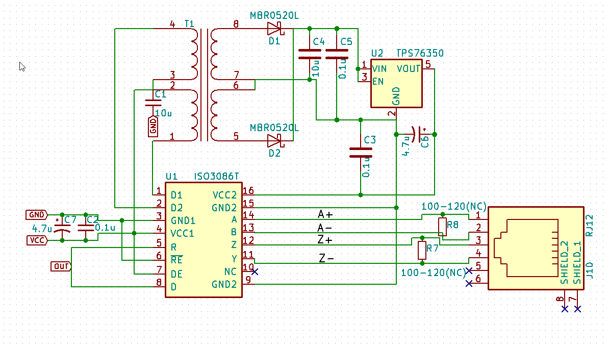
I am trying to build system to send clock signal over Ethernet cable using RS-485 protocol. I prepared proto-board with components mentioned in http://www.ti.com/lit/ug/sluu469/sluu469.pdf.

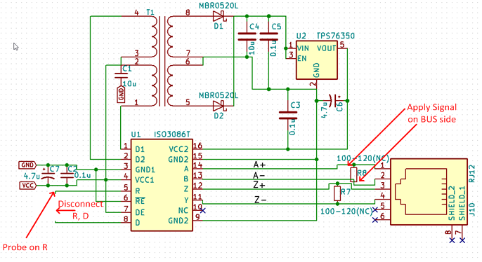
I connected together R and D pins and receiver and driver are always ON. After that I realized that if I touch D pin using unconnected wire (like proto-wires) the high current starts flowing (like 0.8A). Can somebody explain me what is wrong and why it happens? I need to add, that even if high current is not flowing, there is no signal on pin R/D. (I am sure that input signal on RS485 side is present). 

  • Hi Konrad,

    Thanks for posting your question on E2E.

    Could you preform a quick test on your setup? I think this will help us determine what the issue is here. 

    1. Disconnect R from D
    2. Apply signal on RS-485 BUS to A/B
    3. Probe signal on R

    I want to see if you can see a signal on R if R is not connected to D. 

    See figure below:

    Best regards, 

    Dan

  • Hi Dan,

    I did the steps as you mentioned. The signal is not present on R port. I can still drive high current touching D pin. I've done some additional tests and i am sure that it is not because there are bad connections. 

    High current "feature" appears only if I touch it using something metallic.

    Best regards,

    Konrad

  • Hi Konrad,

    This is interesting.

    Can we do a few quick sanity checks on your system?

    1. Can you ensure that the chip you are using is ISO3086T (We've had a customer in the past accidentally use ISO3086, and since they are in the same package they didn't originally notice)?
    2. Can you probe Vcc1, Vcc2 and ensure that they look like clean 5V power supply signals?
    3. With the D, R loop broken as described before, can you apply a signal to D and see it on the bus?

    It might help if I could see a picture of the board. It's not essential at this point, so if you are not comfortable uploading a picture of the board to a public forum, no problem. 

    Best regards, 

    Dan

  • Hi Dan,

    1. It is for sure ISO3086T,

    2. Vcc1 is 3.3V and Vcc2 is 5V,

    3. Signal not appears on the bus.

    I removed that IC and replace it with new one. And now it's works.

    But still we don't know why and how it goes to "high current" state. And how to avoid it. Is it safety to connect directly D and R pins? 

  • Hi Konrad,
    Thanks for checking those things. I've never shorted D and R directly, so I'm looking into this now.
    You said you replaced the IC and now it works. By that, do you mean communication in both paths works? Are you still seeing the high current "feature" with the new part?
    Best regards,
    Dan
  • Hi Dan,

    Yes, after I replaced the IC, communication works in both paths. And now high current "feature" disappeared.

    Best regards,

    Konrad
  • Hi Konrad,

    I'm not exactly sure what happened to cause this issue in the first place. It sounds like the device was damaged at some point.
    Did you conduct any high voltage tests on the part before the problems started occurring?
    Or perhaps there was some damage that happened during soldering?
    I suppose it's possible that Vcc1 may have been shorted to R, since those pins are next to each other. Shorting Vcc1 to GND could cause high currents.

    Best regards,
    Dan
  • Thank you for help :)
    Best regards,
    Konrad