This thread has been locked.

If you have a related question, please click the "Ask a related question" button in the top right corner. The newly created question will be automatically linked to this question.

TPS65986: Using GPIOs to communicate with system battery charger

Part Number: TPS65986

Hi Team,

I am planning to use the TPS65986 USB-C PD Controller and the BQ25703 on my design. I are struggling however to figure out how to communicate the amount of available current from the PD chip to the battery charger.

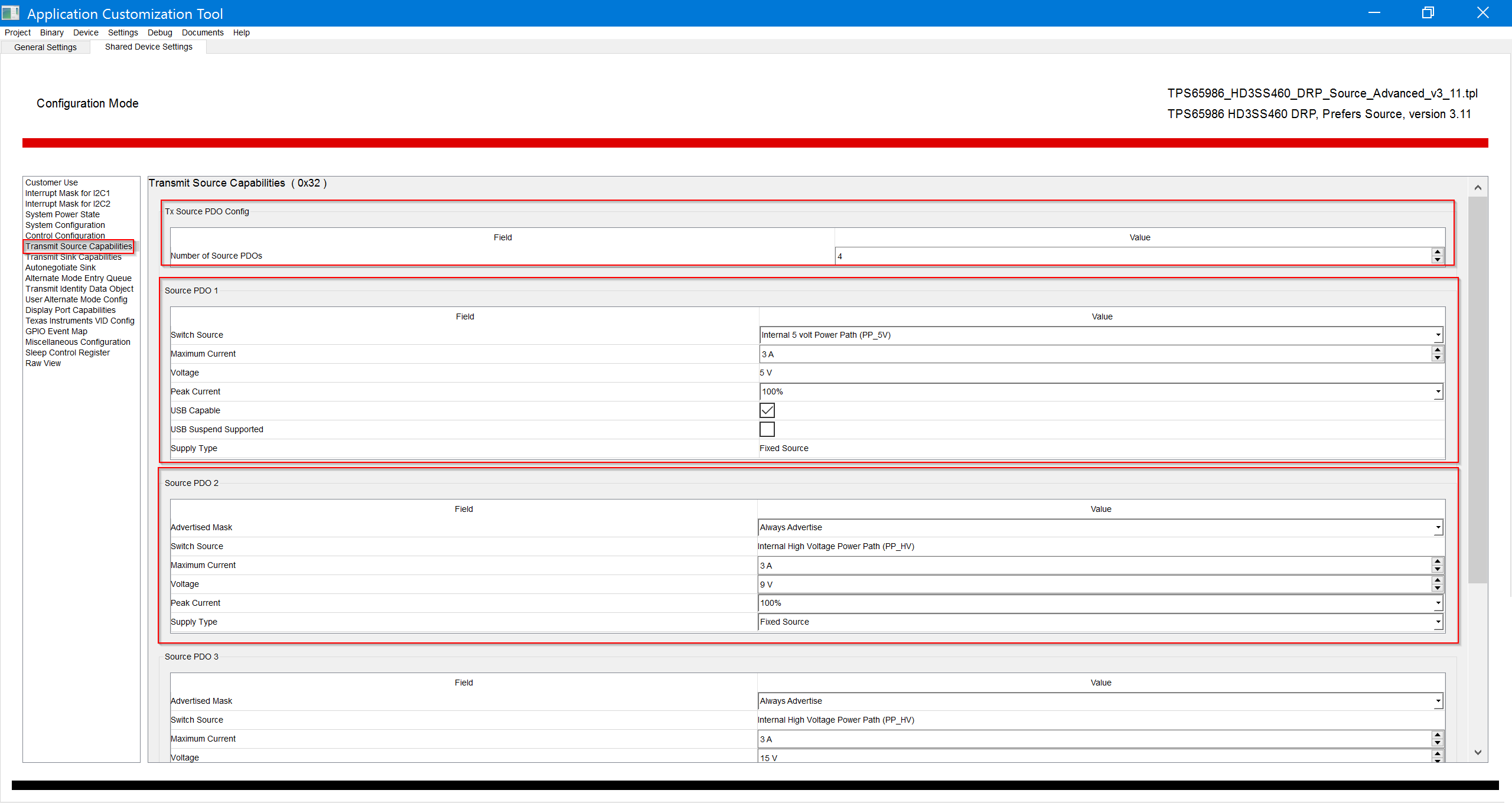
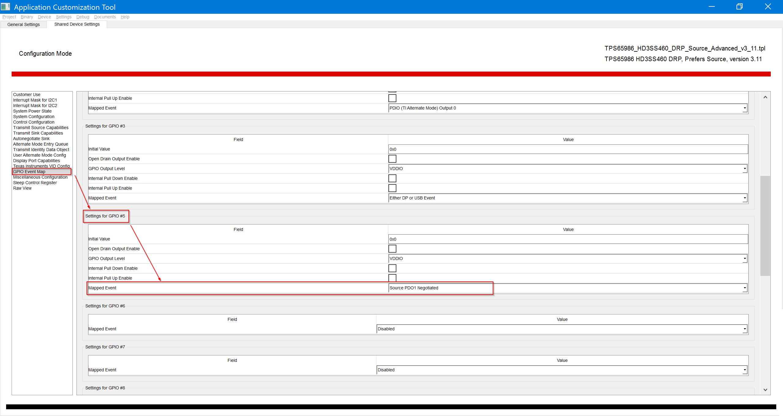
I would like to use the GPIOs on the TPS65986 to set the voltage on the ILIM_HIZ pin using a resistor network. The problem is that there doesn’t seem to be any output events that allow us to get the negotiated PDO/current level onto the GPIOs of the TPS65986.

Does TI have a recommended way to get these products to work together without resorting to an MCU?

Thanks for the support.

Regards,
Hayden

  • EDITED version (5/1/18):

    Hi Hayden,

    The voltage and current of TPS65986 can be configured in TPS6598x Configuration Tool.  One can add the PD voltages (5V/9V/15V/20V for PD spec) and current by configuring the sourcing/sinking capabilities in the Customization Tool GUI. 

    If TPS65986 is configured as the sink, the GPIOs event mapping related to PDOx negation cannot be set. However, one can set up the GPIO event mapping on a sink device by selecting one of the three options:

    1) Sink < 12V Event

    2) Sink > 12V Event

    3) Sink = 12 Event

    If TPS65986 is configured as the source, the GPIOs can be set as the picture below.

    First, set the source capabilities. Here we set 4 PDOs: 5V/9V/15V/20V.

    Then GPIO Event can be set in “GPIO Event Map”. Let’s take GPIO5 as an example and set “Mapped Event” to “Source PDO1 negotiated’’. When 9V is negotiated successfully, GPIO5 will become high and can be an input for other parts.

    Unfortunatly, I’m not sure how BQ25703 works, I would suggest posting it on BQ25703 forum.

    I hope this helps and answers your question, PLEASE select  This resolved my issue  

    Best Regards,

    Hao

  • Hi Hao,

    Thanks for the help here! Unfortunately, I do need to use the device as a sink at times. Are you able to provide any more explanation as to why the GPIOs can't be set when the device is configured as a sink?

    What are your thoughts about using the TPS65983B?

    The TIDA-01627 reference design is close to what we are trying to implement. I have one additional power source (12V @ 1A) that I would like to be able to control as well. Since I would like to source power out of the type-C port while using the 12V @ 1A source to charge my battery I was not planning to use the reverse DC/DC operation of the bq25703 and instead source power from a dedicated 5V supply via the PP_5V path.

    Could the TPS65983 be configured to support that? If so, how?

    Regards,
    Hayden

  • EDITED (5/1/18):

    Hi Hayden,

    TPS65983B is used to build Intel thunderbolt ecosystem only. The exact reference design for a TBT ecosystem is provided by Intel. If the customer is not building a TBT ecosystem, then the TPS65983/B is NOT recommended. The recommended devices for non-TBT ecosystems are TPS65981/2/6. I would recommend the TPS65981 since it comes with an FTDI board to configure application needed through the GUI. 

    One more thing, the voltage values needed to follow USB-PD specs are 5V/3A, 9V/3A, 15V/3A, 20V/5A (would need a 5A active/e-marked cable). A 12V source/sink in reference to VBUS is against PD spec.

    For more info on PD specs, please visit usb.org. 

    I hope it helps and solves your problem, PLEASE select  This resolved my issue  

    Best Regards,

    Hao