Because of the holidays, TI E2E™ design support forum responses will be delayed from Dec. 25 through Jan. 2. Thank you for your patience.

This thread has been locked.

If you have a related question, please click the "Ask a related question" button in the top right corner. The newly created question will be automatically linked to this question.

SN65HVD75: SN65HVD75 lock up issue

Part Number: SN65HVD75

Hi we have a major issue wth the SN65HVD75 parts. We have one main board and 32 output boards which each plug into the main board. We are running at 500kBaud.

In normal mode, the program runs well and there are no problems after a few hours.

In Special diagnostic mode which is where we send a lot of data (and there may be a few collisions), the RS485 bus fails after around 5-10 minutes. When failed, we can see that the A bus pulls high to 3.3V and the B bus pulls down to around 0.3V, and the output is wrong - mainly due to the failsafe voltage (where there is no driver on the RS485 line) being the wrong level.

We currently have no termination resistor, and a 10k pull up on A and 10 k pull down on B. The output boards are maybe 25cm from first to the last board.

Another complication is that we have a ground current sense resistor on each Output board (3.3R with 25mA for ~75mV) so that each Output boards see A and B as a slightly negative signal of around -75mV when low.

Any and ll help would be much appreciated. We have spent a lot of time on this issue and managed to get nowhere over the last week.

Are there any erratas or know problems with these chips? Thanks

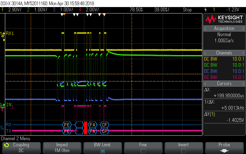
Here is a screenshot of the RS485 bus in failed mode:

Yellow = R output

Green=A

Blue = B

Pink=?

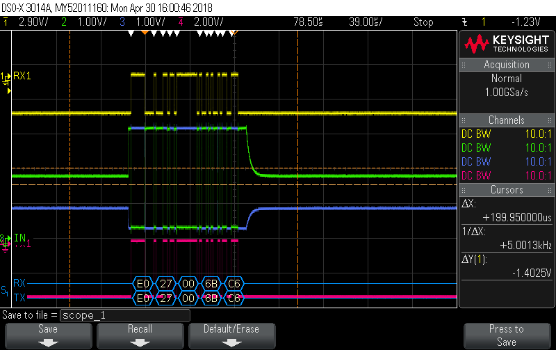
Below is a screenshot of the RS485 bus in working mode after a power on/off cycle

Yellow = R output

Green=A

Blue = B

Pink=?

  • Hello Fergus,

    Thank you for your question. I am unaware of any published errata for the SN65HVD75. To help us understand your failed condtion better, could you provide some clarifying information for me?

    Can you provide a block diagram that shows the connections of the output boards to the main board?

    Could you provide more information about your "Special diagnostice mode"? In this mode, are the drivers or receivers ever disabled? You mentioned that you have an idle bus at some point when no driver is driving.
    You also mentioned that there may be some data collisions in that mode. Is that a condition when multiple drivers are transmitting? That may account for the intermediate behavior of the bus pin signals from your first scope shot.
    Would you be able to provide some scope shots of your DE and REB pins during this failed mode (if they change at all)?
    You mentioned that the bus fails after 5-10 minutes during the diagnostic mode. Is this behavior consistent? Is there any configuration of the network that changes between the beginning of the diagnostic mode and the time of the failure?

    In your second scope shot, the A and B pins fully toggle across the output range (~3V). But in the first scope shot, the A/B pins only toggle to some intermediate voltage level. Can you provide the voltage levels of the A and B pins in your first scope shot?

    It looks like the pink signal may be labeled TX1. Is that correct? Just as a note, the RX1 signal closely matches the pink signal from both scope shots.

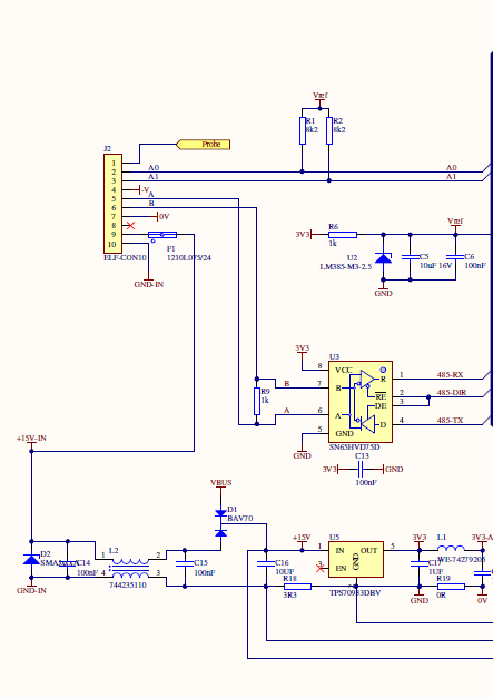
    Could you provide a schematic or block diagram that includes the ground sense resistors that you mentioned, as well as the pull up configuration that you described for the A and B pins?
    Is there a reason why you are not implementing a termination resistor for the network?

    Best Regards,
    Max Megee
  • Hi Max

    Thanks for the reply.

    Please find below part of the schematic which shows the Output board and power supply - please note the 3.3 ohm resistor in the ground line for current sensing. There are 32 output boards plugged in vertically to the Main board. The Main board has the same SN65HVD75 chip. We removed the termination resistor since we realised that having 33 of these 1k resistors in parallel became around 30 ohms. There are currently now termination resistors, but we did yesterday add a single 10k pullup to the A line and a 10k pull down on the B line. Without the pullup and pull down, the green and blue A and B lines float at the same voltage when idle (which is around 1V).

    Our software diagnostic mode is where we send a receive a lot of information. For some reason,the problem happens in this mode and not in the normal run mode. For 80-90% of the time, the data bus is idle. I am out of the office today but the DE/REB pin is always low for the two screenshots above (this is data from the main board so the DE/REB line will be high on the Main board for this data packet).

    Yes, the pink and yellow signals were from the same spot - 485-RX on the Output board.

    With the termination resistor, the RS485 network is only 25cm long so we understand a termination resistor is not needed. If there was some way to determine an optimal value of termination resistor, we would be very happy to investigate that and put on that resistor. Thanks

  • Hi Max

    Also, here is another point for consideration.

    All the units were running with 1k termination resistors on every board. 33x 1k termination resistors in parallel gives an effective termination resistance of 30ohms which means the RS485 driver was outputting around 100mA into 3.3V.

    The output drivers on these chips are only rated at 60mA. Do you believe that these chips would be partly damaged and in you opinion, do you think it would be beneficial to replace all these chips and test the circuit again for correct operation? Thanks

  • Fergus,

    Thank you for the details.  The output drivers for each transceiver are current limited to up to 160mA during a bus fault, so 100mA draw on the bus should not damage the devices.

    A couple more questions based on your feedback.

    Are you sure that the Green is the A output and the Blue is the B output?  From the scope shots, it looks like it should be the other way around.  For (A-B)>-20mV, the RX pin should output High, and for (A-B)<-200mV, the RX pin should output Low.  It looks like the Green lines should be the B pin, and the Blue lines should be the A pin, unless there is an inverter on the RX path before the Yellow scope was taken.  This is true for both normal and diagnostic mode scope shots.

    The intermediate voltage  levels on the A and B pins during diagnostic mode is what concerns me.  If the bus was truly idle, then your pullup resistors would operate on the bus signals.  Can you check and see if any other node in the network besides the Main Board is trying to drive on the bus during this mode?  You can put a scope on the DE/REB signal for the other Output Boards during this mode to see if any of them attempt to drive the bus while the Main board is driving.

    The RX pin is only switching High when the Blue signal is drifting slightly higher than Green during these intermediate bits.  Can you provide the specific voltage levels during these intermediate states on your diagnostic mode scope shot?  See the boxes I highlighted in Red below.  It looks to me that the receiver may be responding normally to the bus voltage levels, but we need to identify why the bus lines seem to be in contention.

    Best Regards,

    Max

  • Hi Max

    With the yellow signal, this is inverted. We set this line to inverted since the Serial function is expecting RS232 levels not the TTL serial levels being shown which are the inverse of RS232.

    Yes, that is quite possible. I will go in tomorrow and try that. We did do a recent software change to use transmit interrupts and had some issues with the interrupt setting the DIR line low correctly. It now looks likely that there are still some software issues which explains why the old firmware ran fine and we are only seeing this issue now. 

    The easiest way to test this is to remove all the boards while the issue is happening to find out if an output board is transmitting at the same time. I will be back in the factory tomorrow. Thanks

  • Hi Max, yes definitely a bus contention issue. We did find one Output board would lock up and hold the DE pin high causing this issue.

    Thanks forf your help in isolating this issue.