This thread has been locked.

If you have a related question, please click the "Ask a related question" button in the top right corner. The newly created question will be automatically linked to this question.

DS90UB913A-Q1: Communication over the FPD-Link III

Part Number: DS90UB913A-Q1
Other Parts Discussed in Thread: DS90UB914A-Q1

i want to understand the communication over the FPD-Link III.


For the following measurement these settings were adjusted.

Serializer:            DS90UB913A

Deserializer:      DS90UB914A

PCLK:                    20MHz


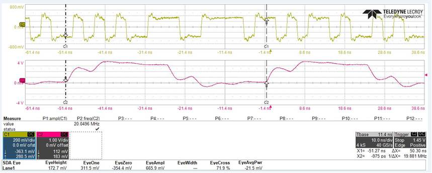
The Chanel 1 shows die CML monitor and the Channel 2 the PCLK. (Measured with Teledyne SDA 820Zi-B)


The datasheet ds90ub914a-q1.pdf an the TI FPD-Link University gives the following information:


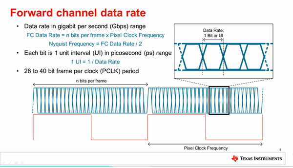
8.3.1 Serial Frame Format

The High Speed Forward Channel is composed of 28 bits of data containing video data, sync signals, I2C and

parity bits. This data payload is optimized for signal transmission over an AC-coupled link. Data is randomized,

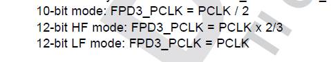
balanced and scrambled. The 28-bit frame structure changes in the 12-bit low frequency mode, 12-bit high

frequency mode and the 10-bit mode internally and is seamless to the customer. The bidirectional control

channel data is transferred over the single serial link along with the high-speed forward data. This architecture

provides a full duplex low speed forward and backward path across the serial link together with a high speed

forward channel without the dependence on the video blanking phase.


On the scope I only count 18 bits per frame, not 28 as expected. Where is my mistake?


Could you please show me the decoding of a frame. How many bits are using for videoinformation, how many
for I2C, how many for for sync and how many bits are use for parity check?


Do you use 8b/10b coding for sending the information balanced?

  • Hello,
    The 913A/914A FPD-Link devices have 28-bit frames that includes 24 data bits (18-bit RGB+3 + I2C), 2 clock bits and 2 link overhead bits. All the payload bits are randomized, balanced (not 8b/10b, another type of encoding) and scrambled.
  • Hello Palaniappan Manickam,

    thank you for the answer.

    when I try to count the bits in the scope, I only count 18bits.
    (See the picture in the previous mail)

    I choose the 12 bit high mode, thus we only send 12bit RGB not 18.

    What is the width of one bit in my case?
    Why do I count only 18 bits in one clock cycle?

    Greetings,

    Muhammed Guengoer

  • Hello Muhammed,

    there are 28-bit within every FPD3_PCLK.  But depending on the Serializer mode, the FPD3_PCLK vs PCLK relationship may vary:

    Based on the measurements, it looks like your system operates in 12-bit HF mode.

    The Raw Forward channel frame structure consists of embedded clock signals (clk0-clk1), synchronization bit (DCA), DC-balancing bit (DCB), control bit (I2C), 1-bit CRC (parity) and 22 bits of data payload.

    The Raw10 mode with 8-bit option is not supported on the 914A. It is supported on the 954 and 964 Deserializers.