This thread has been locked.

If you have a related question, please click the "Ask a related question" button in the top right corner. The newly created question will be automatically linked to this question.

SN65DSI86: Color bar can display, but MIPI source can't display

Part Number: SN65DSI86

Dear TIer

My customer recent work on SN65DSI86 and TI AA FAE Emma had respounse some setting for customer.

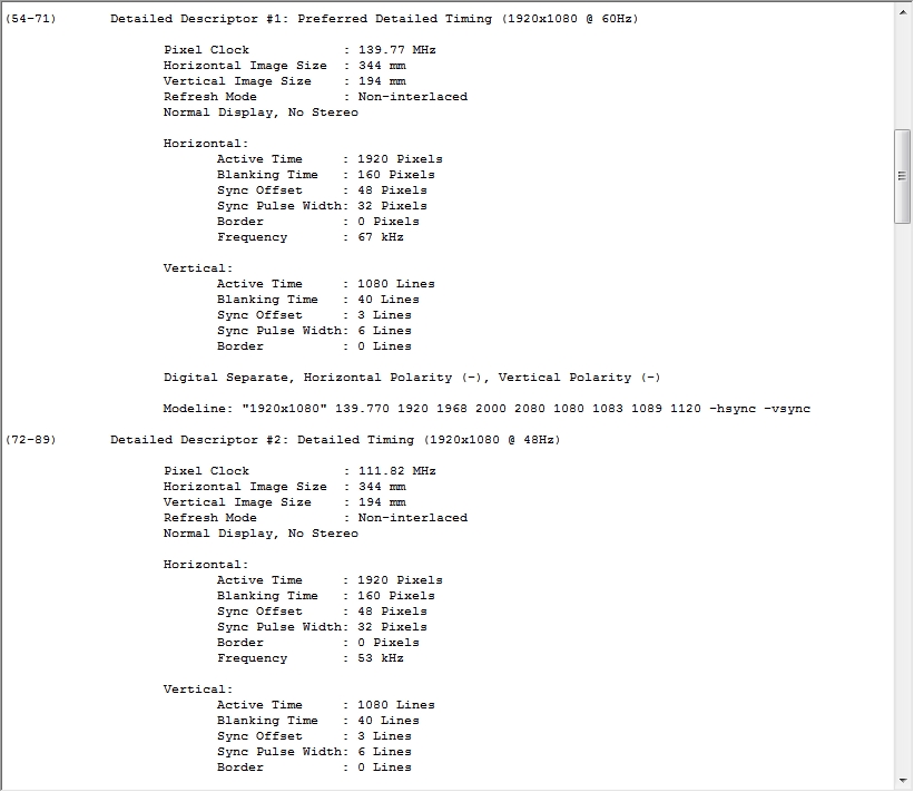
For now customer can display color bar pattern, but can't display MIPI source signal.( We measure the MIPI signal have data)

Circuit use 27Mhz christal and can measure clock so setting is REFCLK mode. And the panel format is 1080P RGB666 format.

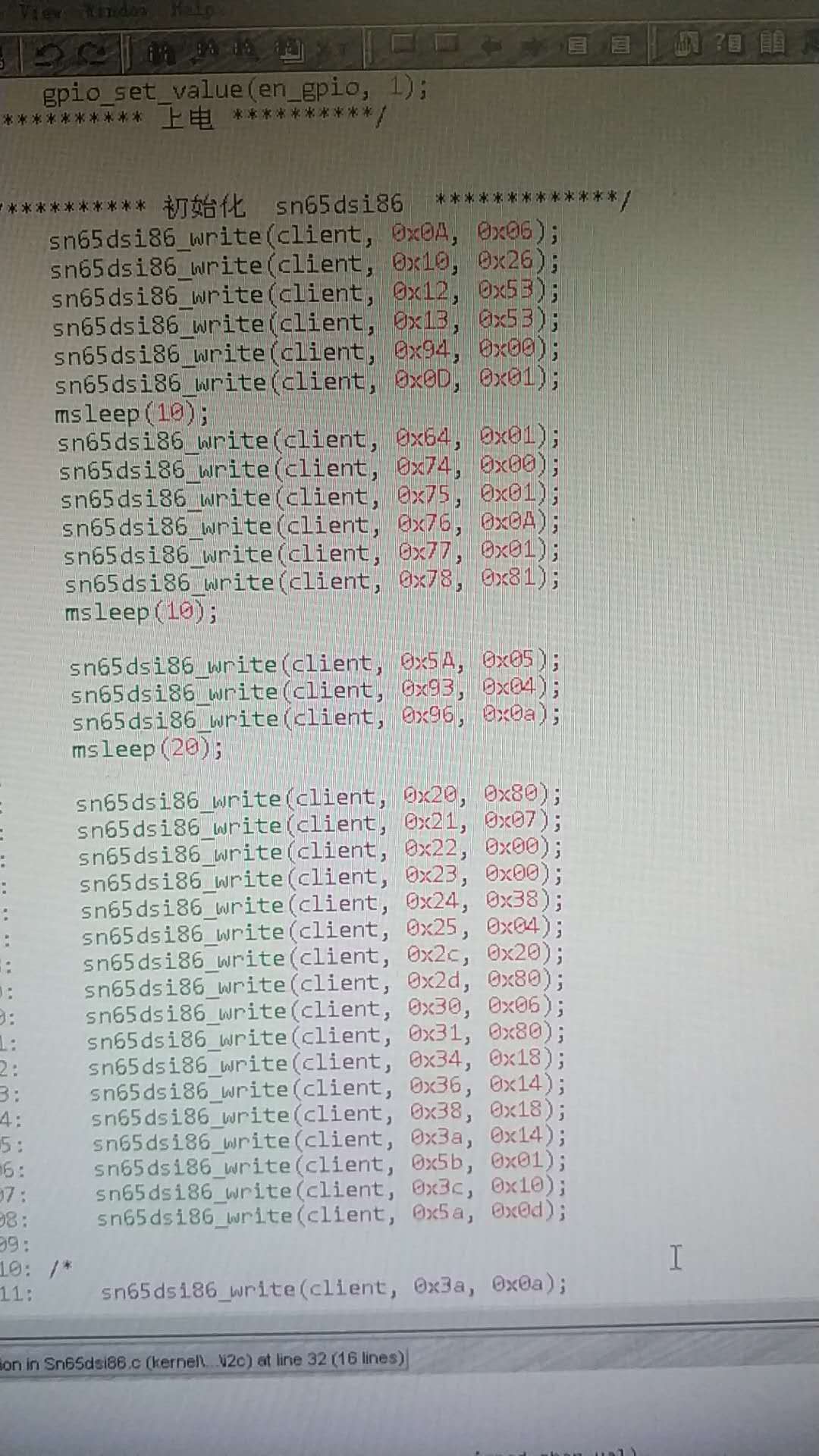
We had try several settings change, but still not good.

Do you have some experience ideas can suggest us how to check and debug settings & registers states?

Thanks so much 

  • Bruce,

    Is it possible for you to send me the EDID for the panel being used?
  • Hi Malik

         Thanks for your reply! Following picture is the panel EDID read data. And the next data was reply from Campbell 4/28 I think. 

    We use the setting but can't display even color bar. Customer need to set 0x96 be 0x01 can display out color bar.

    I also ask them modify like 0x5a form 0x0D to 0x0C, and 0x12 to 0x42 or 0x43 ( RGB666 can calculate 148.5Mhz*18/8=334.5Mhz=42H)  

    Can I got some useful information from 0xF0~0xFF int reg ?

    //Offset, Data
    
    0A	2
    
    10	26
    
    12	53
    
    13	53
    
    94	80
    
    0D	1
    
    64	1
    
    74	0
    
    75	1
    
    76	0A
    
    77	1
    
    78	81
    
    
    5A	5
    
    93	20
    
    96	0A
    
    
    20	80
    
    21	07
    
    22	0
    
    23	0
    
    24	38
    
    25	04
    
    2C	20
    
    2D	00
    
    30	06
    
    31	00
    
    34	50
    
    36	1F
    
    38	30
    
    3A	03
    
    5B	0
    
    3C	0
    
    5A	0D
    

    And the follow picture is customer setting structure. We had do some modified. I don't have final setting picture. I had find some setting on E2E, seems like this.

    Please help us check where could be wrong.

    Thank you so much!

  • Bruce,

    Try changing the resister values as listed below, this may help gaining the proper functionality for your panel.

    0x0A = 0x02
    0x12 = 0x3E
    0x13 = 0x3E
    0x2D = 0x00
    0x31 = 0x00
    0x34 = 0x50
    0x36 = 0x1F
    0x38 = 0x30
    0x3A = 0x03
    0x93 = 0x20

    You are using RBR, HBR or HBR 2? To confirm your only using DSI A Lanes correct?

    Could you post a block diagram of the application? This will help debugging some of the errors found in the 0xF0-FF registers.