This thread has been locked.

If you have a related question, please click the "Ask a related question" button in the top right corner. The newly created question will be automatically linked to this question.

DS64BR111: Intermittent link problems

Part Number: DS64BR111

We have developed a COM Express Carrier board with a SATA III interface to connect to SSD. The carrier board hosts a COM Express module with Intel CPU. On the carrier board itself is DS64BR111. The overall link is: Intel CPU -> COM Express Connector -> DS64BR111 -> 7 Pin SATA Connector -> Cable -> SSD.


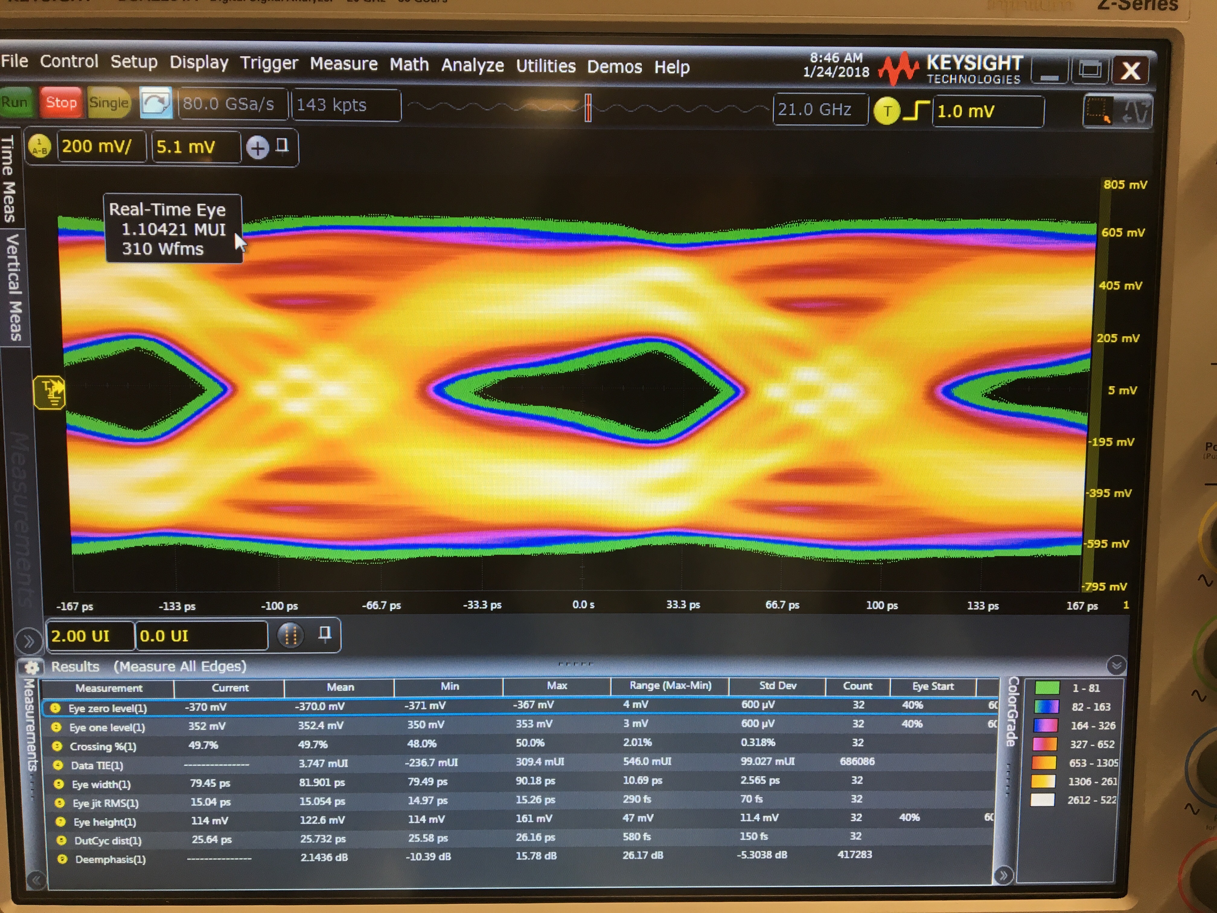
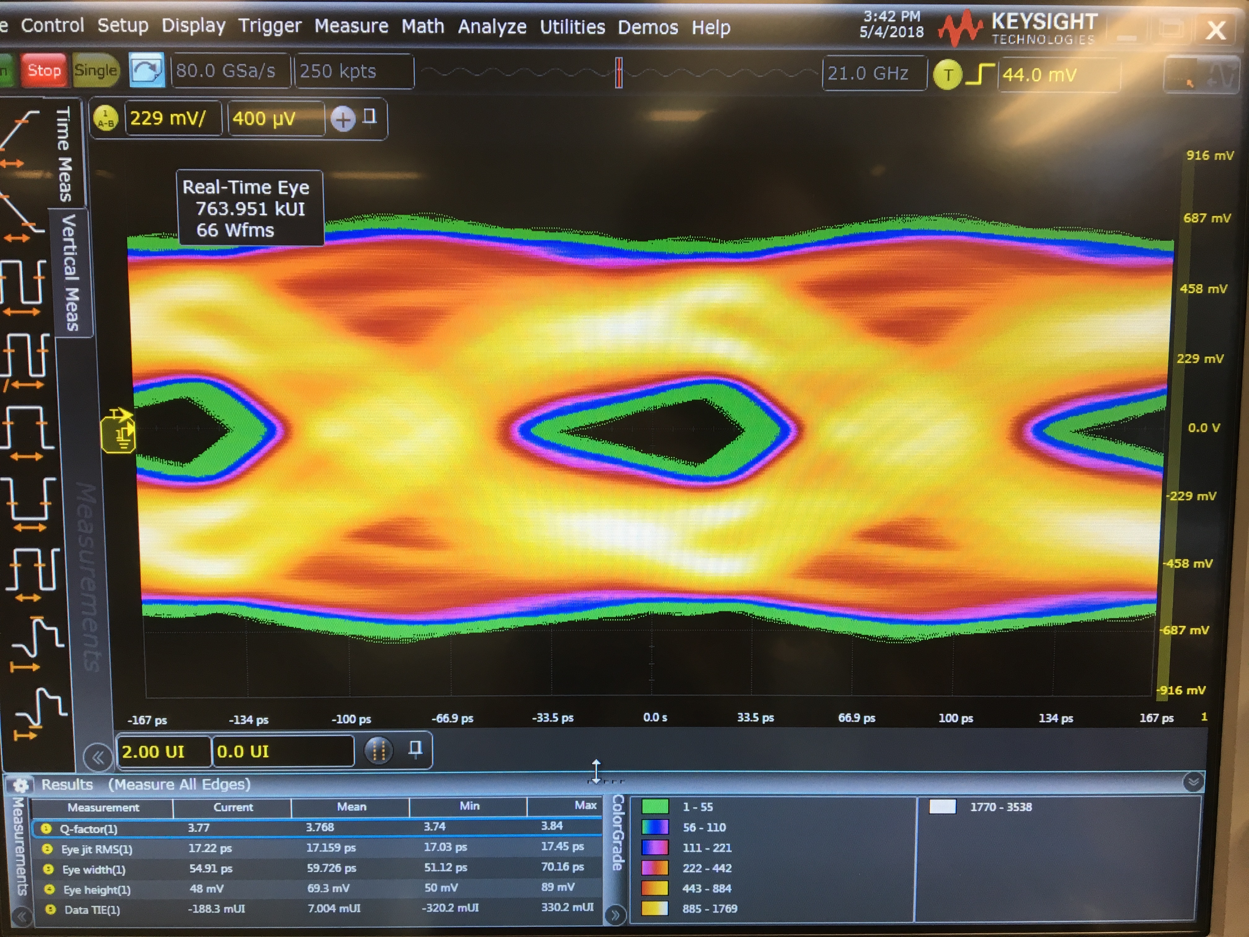
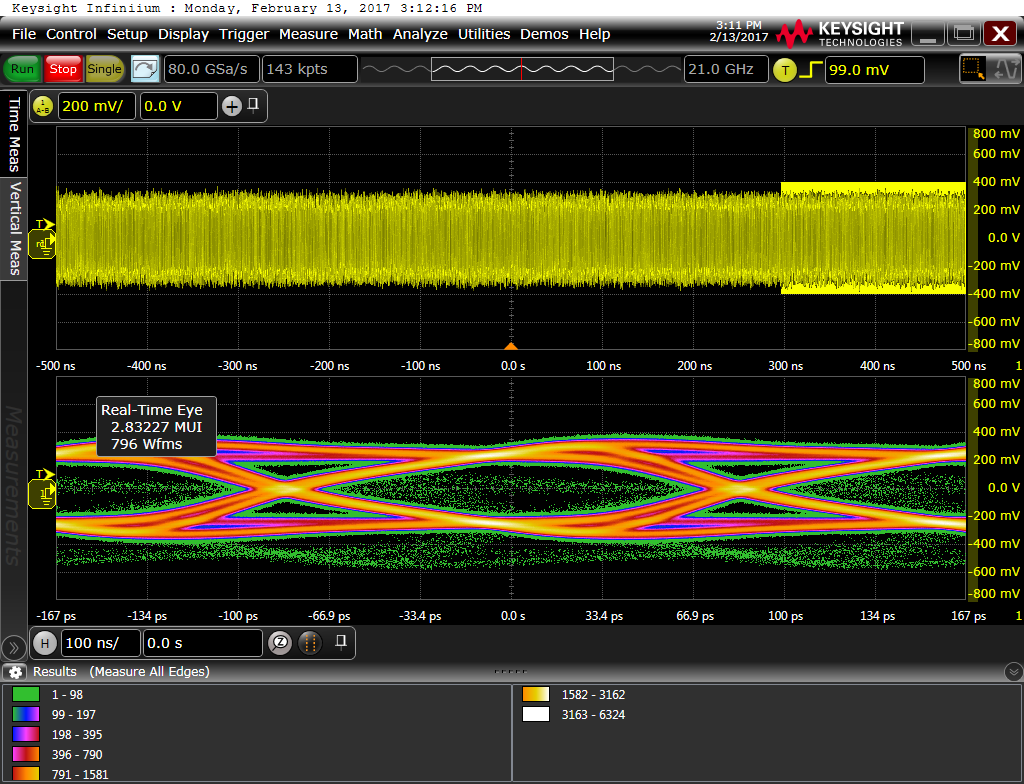
We have experienced intermittent problems with reliability of SATA link between Intel CPU and SSD. We are in the process of determining root cause. One area of concern is signal integrity of SATA link; we have seen errors reported in OS and SMART statistics of drive that indicate there are occasional CRC errors detected by the drive.  Sometimes the drive is not detected by the OS at boot time, and other times it is detected and later has errors which causes the filesystem to be remounted read-only. I have tried to tune the link via DS64BR111 settings, but I haven’t been able to measurably improve the situation.

Any help here?  We may want to pull this over email as well.

Thanks,

David

  • Hi David,

    Here is a Pin + SMBus configuration that I use in SATA systems which exhibit OOB signaling issues like you have described.

    PINS:

    ENSMB: 1K to VDD (VIN if using 3.3V mode with internal regulation)

    MODE: 1K to GND 

    VOD_SEL: 1K to GND

    TX_DIS: GND


    REGISTERS:

    Register               Write Data

    0x06                       0x18       /* Enable SMBus registers

    0x08                       0x04       /* Override output drive mode

    0x0D                      0x01       /* Lock Signal Detect “on” CHA

    0x0F                       0x01       /* 6.5 dB EQ gain

    0x10                       0xAD     /* Linear output drive

    0x11                       0x80       /* 0 dB DEM

    0x14                       0x01       /* Lock Signal Detect “on” CHB

    0x16                       0x01       /* 6.5 dB EQ gain

    0x17                       0xAD     /* Linear output drive

    0x18                       0x80       /* 0 dB DEM

    0x23                       0x04       /* VOD = 800mV

    0x2D                      0xA5      /* VOD = 800mV

    0x4C                      0x01       /* Disable DC offset correction

    Regards,

    Lee

  • We must use Pin-mode for configuration; SMBus is not available. We use 3.3V mode of operation.


    Our configuration is:

    ENSMB: 1k to GND

    MODE: 1k to 3.3V

    VOD_SEL: 1k to GND

    TX_DIS: 1k to GND


    I see that our MODE setting differs; HIGH = Continuous Talk, LOW = SAS Mode, Fast OOB. (I also see mention here that MODE = 0 is important for SATA: e2e.ti.com/.../1183105. Do you think this is a likely culprit for drive detection after system power on?  We have had mixed results -- we can go for hundreds of successful boot sequences without failure, and then be hit with a rash of failures for no good reason.


    Does the MODE setting have any impact on communications after the link is established? If not, we may have multiple issues since we have also encountered PHY CRC error messages (thrown by Linux kernel) which I believe are related to signal integrity. I have probed inputs/outputs of chip on high speed scope and the buffered/driven output of DS64BR111 don't appear to be great. I have attached a photo of what I am seeing.


  • Also, I think the design original was set with MODE: 1k to VDD based on recommendations here: e2e.ti.com/.../1958962
  • Hi Joushua,

    What are the EQ and DEM configuration pin settings? This signal looks over equalized. We can start by improving the waveform and see if it eliminates the errors you have seen reported by Linux.

    Regards,
    Lee
  • The overall topology is in David's original post. The cable is 12" long.

    Channel A is SSD -> COM Express Module
    Channel B is COM Express Module -> SSD

    CHA/IN: EQ = 8.5dB (EQA0: 1k to VIN/3.3, EQA1: 1k to GND)
    CHA/OUT: DEM = -3.5dB (DEMA: Float)
    CHB/IN: EQ = 0dB (EQB0: 1k to GND, EQB1: 1k to GND)
    CHB/OUT: DEM = -6dB (DEMB: 20k to GND)


    The trace previously shown is on the far end of CHB/OUT (probing at the caps next to SSD controller).

    EDIT: Added missing EQ settings

  • Hi Joshua,

    I recommend to reduce the CHA EQ = minimum (EQA0 = 1k to GND) and the CHB DEMB = -3.5 dB (Float)  to see if some of the over equalization can be removed.

    With only pin control to manipulate the DS64BR111 I would recommend to try a different approach.

    MODE = High

    VOD_SEL = High (uses a non limiting output style which can help OOB noise transmission)

    DEM = Float

    SD_TH = Low

    You can also try the above settings with MODE = Low to see if that can help in your application.

    Regards,

    Lee

  • SD_TH to LOW (from Float) would be increasing the thresold level for LOS -- what impact does this have on the link?

  • Hi Joshua,

    Changing SD_TH to "0" increases the Signal Detect threshold.  By making the signal detect less sensitive it is easier to reject idle "noise" and correctly re-transmit OOB configuration pulses.

    Regards,

    Lee 

  • I have made the changes suggested.

    Functionally the design still booted. However the eye opening seems to have closed more relative to my previous observations -- height and width.

    I assume that some differences in eye measurements can be attributed to differences in probing (though the same test equipment was used); but the overall characteristics of the eye don't seem to have changed significantly.

    I have attached another screenshot.

  • Joshua,

    Based on the eye crossing there is a large amount of deterministic jitter which cannot be compensated for with a linear equalizer.  This could be the probing location, but I think there is also some PCB structures impacting the eye quality.  Could you send me some pictures of the system with DS64BR111 locations and measurement points annotated?  It would also help to get the native board file to look at the PCB in detail.  send to lee.sledjeski@ti.com

    Regards,

    Lee

  • For reference, here is what the eye looks like at the input to the redriver (INB):

  • Moved thread to email to exchange more detailed information.

    Regards,

    Lee