This thread has been locked.

If you have a related question, please click the "Ask a related question" button in the top right corner. The newly created question will be automatically linked to this question.

SN65DSI84: Can't get lock

Part Number: SN65DSI84

Hi team,

My customer is using SN65DSI84 to convert DSI to LVDS. We followed the setup sequence below but can’t get lock. Could you help check what’s the matter? We also want to know in what condition can we get lock? As long as our DSI clock is good? Or the DSI data may also affect lock?

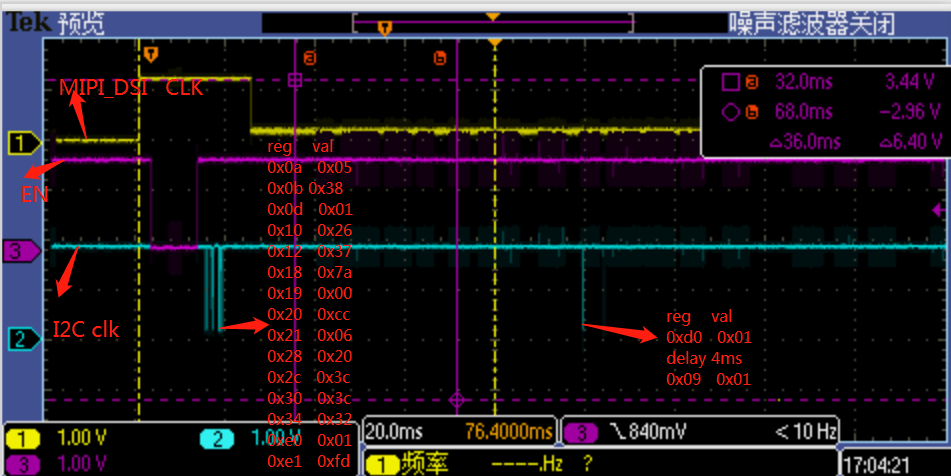
The system is Intel X86 --> DSI84 --> panel. The clk of CSI is about 277MHz, so we set 0X12 to 0x37.

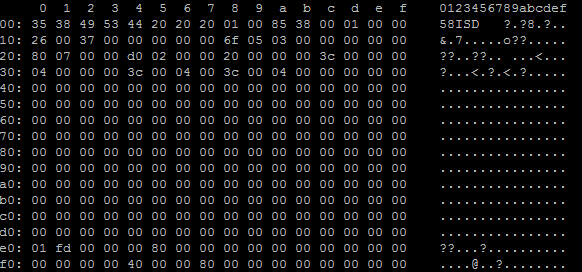
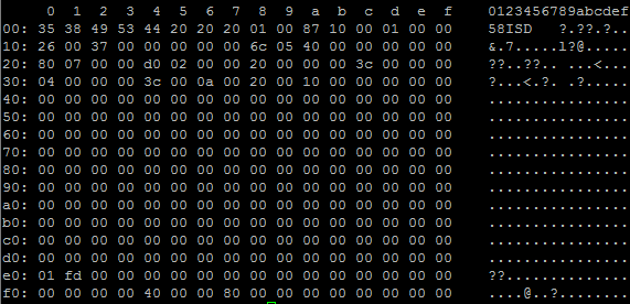
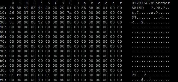
1、The register dump is as below, you can see E5 is 81:

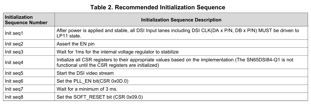
2、Our  initialization Sequence:
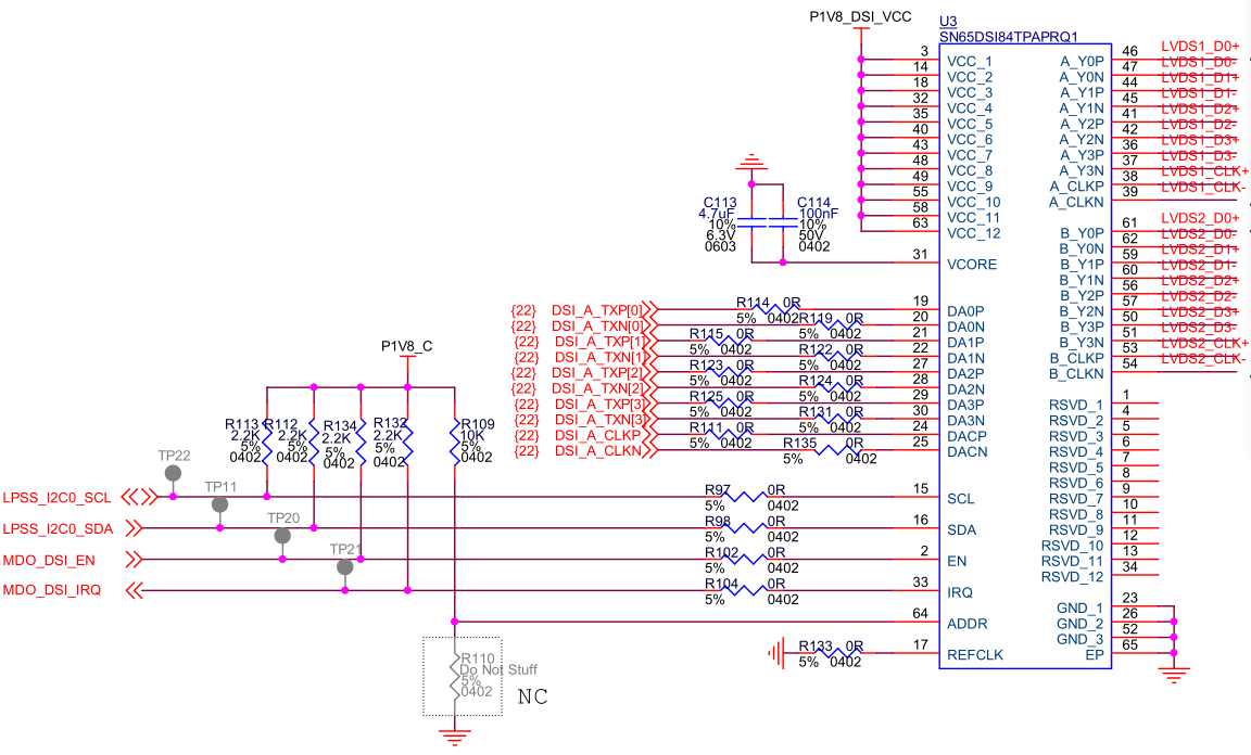
3、Our schematic:

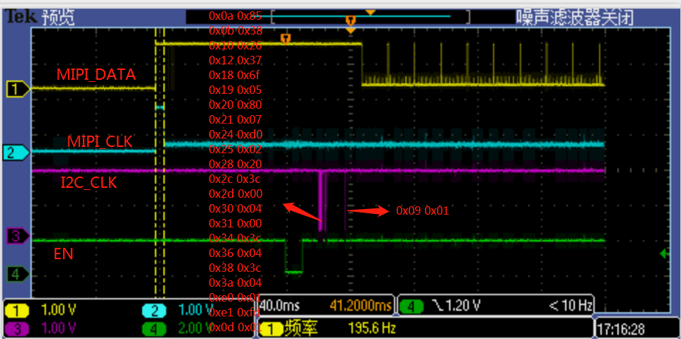
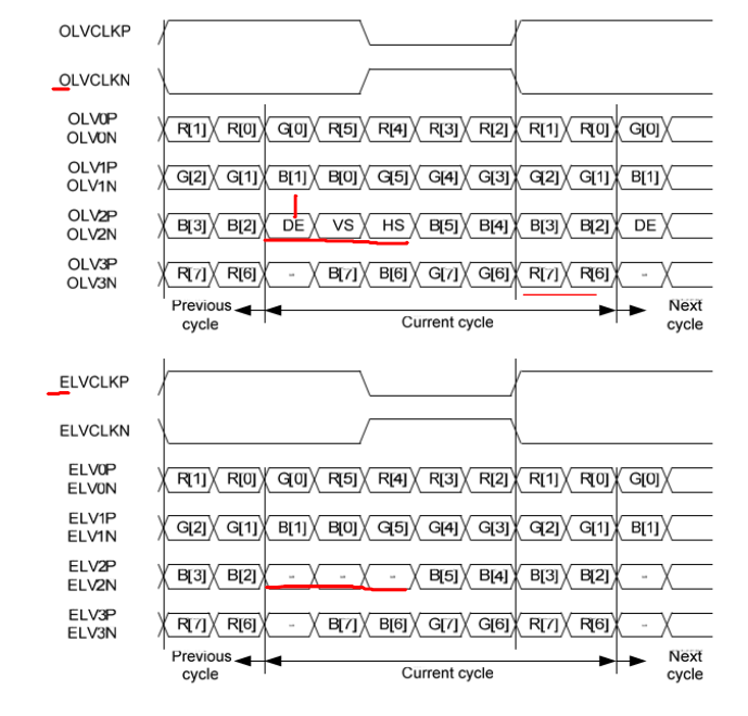
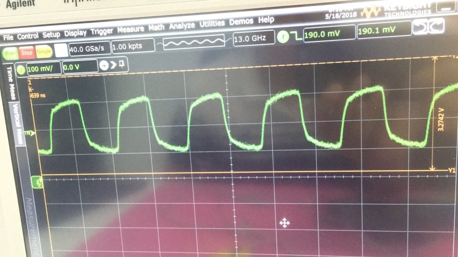
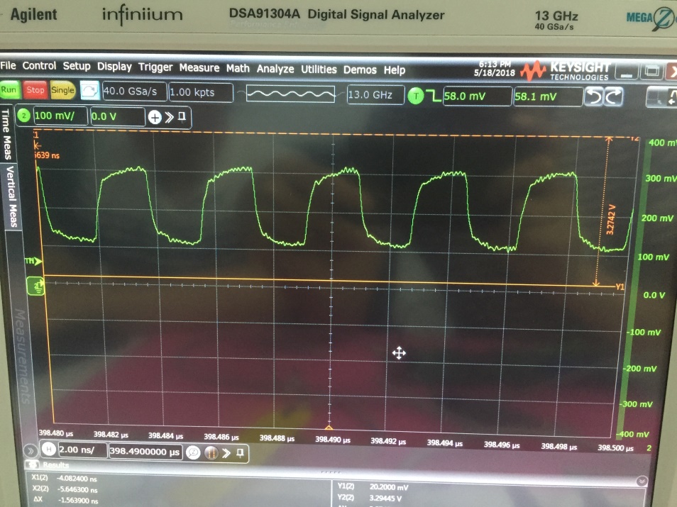
4. Our clock waveform is as below:


 Is there anything wrong with our setup?

Thanks,

cera

  • Hi Cera,

    Register 0xE5 may get set during the initialization sequence. Can you ask the customer to clear the register by writing 0xFF to it before reading it?

    Additionally, is reading this register their only indication of a failure so far? Have they tried hooking it up to their panel or measuring the LVDS clock output?

    Regards,
    I.K.
  • Hi I.K.

    Thanks for your timely help. After cleared the error, we can get lock now.

    However, we still have CHA_SYNCH_ERR, do you have any idea what's the usual cause of this error? Can we monitor the HS/VS by scope?

    Here's the HS and VS setup for MIPI DSI:

    hactive_hi 7,  (ACTIVE_LINE_LENGTH_HIGH)

    hactive_lo 80,  (ACTIVE_LINE_LENGTH_LOW)

    vactive_hi 2,  (VERTICAL_DISPLAY_SIZE_HIGH)

    vactive_lo d0  (VERTICAL_DISPLAY_SIZE_LOW)

    hsync_pulse_width_hi 0,   (HSYNC_PULSE_WIDTH_HIGH)

    hsync_pulse_width_lo 3c, (HSYNC_PULSE_WIDTH_LOW)

    vsync_pulse_width_hi 0  (VSYNC_PULSE_WIDTH_HIGH)

    vsync_pulse_width_lo 4,( VSYNC_PULSE_WIDTH_LOW)

    hblank_hi 0,

    hblank_lo b4,

    hsync_off_hi 0,   //OFFSET

    hsync_off_lo 3c,

    vblank_hi 0,

    vblank_lo c,

    vsync_off_hi 0, ()

    vsync_off_lo 4

    Thanks,

    Cera

  • hi team:

    The register dump is as below, you can see E5 is 80:

  • Hi Cera,

    Can you share the panel datasheet with me so I can confirm the device is configured correctly? You can email it to i-anyiam@ti.com

    Additionally, can you implement this initialization sequence instead of the one currently in the datasheet? This may fix the issue. 

    1

    Power on

    2

    CLK set to HS and  DATA set LP11

    3

    Set EN pin to Low 


    Wait 10 ms

    4

    Tie EN pin to High


    Wait 10 ms

    5               

    Transfer all register settings

    6               

    Set PLL EN register 0x0D to 0x01 to enable PLL


    Wait 10 ms

    7               

    SW Reset


    Wait 10 ms

    8               

    Change DATA to HS

    Regards,

    I.K.

  • hi I.K.

           The  initialization Sequence is the latest,bit 7 of register 0xE5 is set all the time even if I clear it.

  • hi I.K.:

          After set 0x0b=0x10,0x0a=0x87  , we can clear bit 7 of register 0xE5.

          but display is error,Can you see anything wrong with it?

  • Hello,

    From the register dump you provided, it looks like register 0x18 is being set to 0x6F, correct?

    If you take a look at register 0x18 in the datasheet 

    a write of 0x6F to this register means that bits 0 and 1 are being set to 1, and the device is configured using Format 1, where the LSB are transferred to the 3rd LVDS data line. 

    If you take a look at your panel datasheet, your panel is actually expecting the MSB on the 3rd LVDS data line. This means you need to configure the device to use Format 2. 

    So try setting register 0x18 equal to 0x6C and see if that resolves the issue. 

    Regards,

    I.K. 

  • hi I.K:

    The Latest  register dump is as below,but the pannel display still has problems, as shown in the figure above.

     Is there anything wrong with our setup?

    Regards,

    I.K. 

  • Hello,

    Here are a couple of steps to try:

    1. Can you try enabling the test pattern? The procedure for this is on page 14 of the datasheet. This would help isolate the problem.

    2. Can you  configure the CSR settings with the DSI Tuner tool? http://www.ti.com/tool/DSI-TUNER (if some of the screen gets cut off with this one you can try the attached one instead) 

    3. Have you checked the DSI line time? The line time (horizontal sync to the next horizontal sync timing from the APU) on the input is preserved when outputting onto the LVDS interface. The DSI84 doesn't realign timing so if these don't match there will be issues.

    Also, what frequency is the DSI CLK running at, and what frequency is the LVDS clock?

    Regards,

    I.K. 

    https://e2e.ti.com/cfs-file/__key/communityserver-discussions-components-files/138/DSI-Tuner-2.1.exe

  • hi I.K.:

    This problem has been solved, thanks for your support.

  • Hi,

    I'm glad to see that the problem has been resolved. Do you mind posting what fixed the problem for future reference?

    Regards,
    I.K.
  • hi I.KI
    After set 0x34=0xd2,
    0x2c=0xff ,
    0x2d=0x2.
    we can full-screen display.

    Regards,
    linmingchuang